Transmission system and method for assigning transmission channel

a transmission system and transmission channel technology, applied in the field of transmission system and transmission channel assignment, can solve the problems of transmission error, packet loss caused by transmission error retransmission, and inability to complete retransmission, so as to achieve the effect of effectively using communication bandwidth

Inactive Publication Date: 2009-03-05
CANON KK
View PDF4 Cites 114 Cited by
  • Summary
  • Abstract
  • Description
  • Claims
  • Application Information

AI Technical Summary

Benefits of technology

[0007]An object of the present invention is to effectively use communicati

Problems solved by technology

However, since a wireless LAN has a transmission bandwidth not as wide as that of the wired LAN, it frequently causes transmission errors when HD video is transmitted, due to the occurrence of delays and the interference of radio waves under the influence of other traffic.
These transmission errors are inherently caused and cannot be prevented, so that packets lost by the transmissi

Method used


Image

  • Transmission system and method for assigning transmission channel
  • Transmission system and method for assigning transmission channel
  • Transmission system and method for assigning transmission channel

Examples


Embodiment Construction

[0023]The best mode for carrying out the present invention will be described in detail below with reference to the drawings.

Multiplex Transmission System

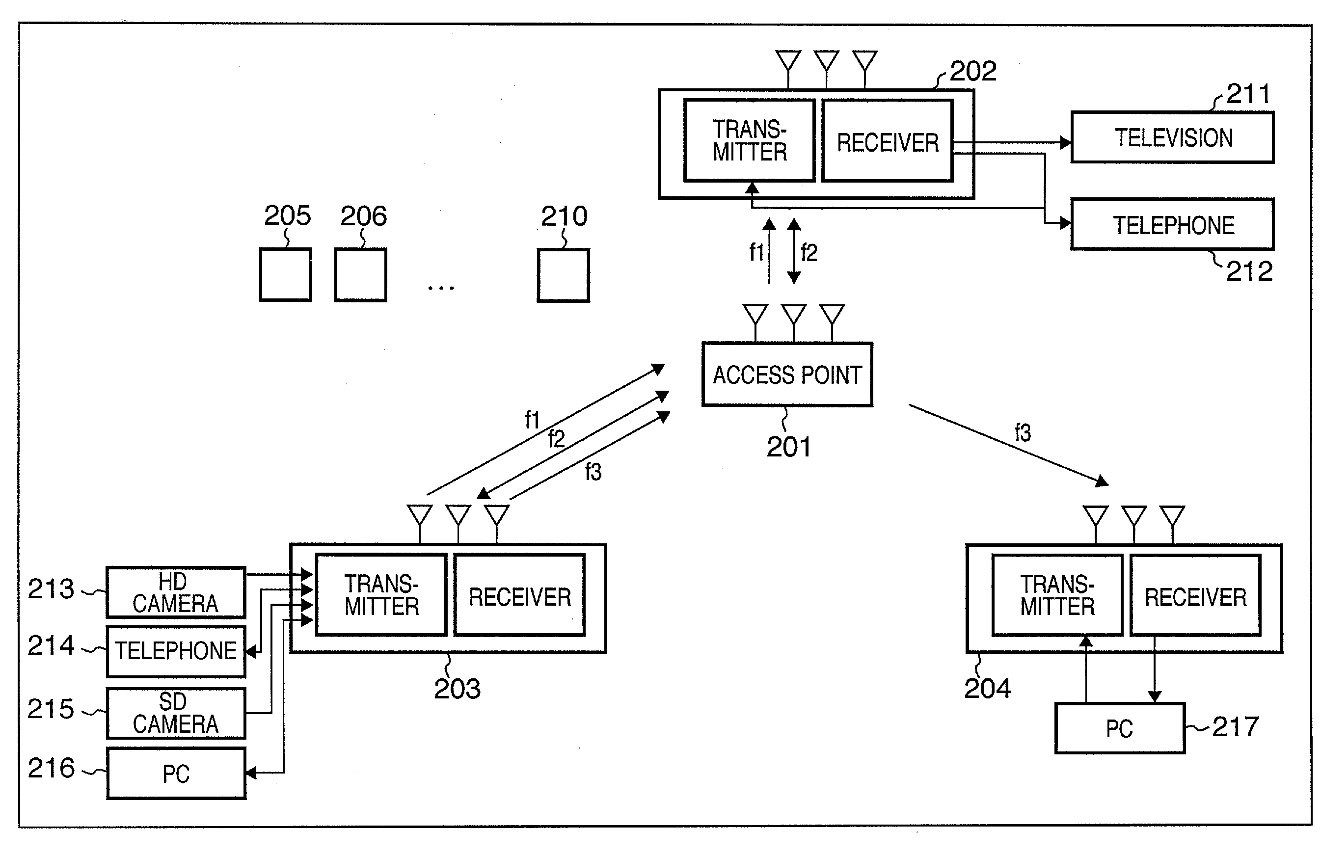
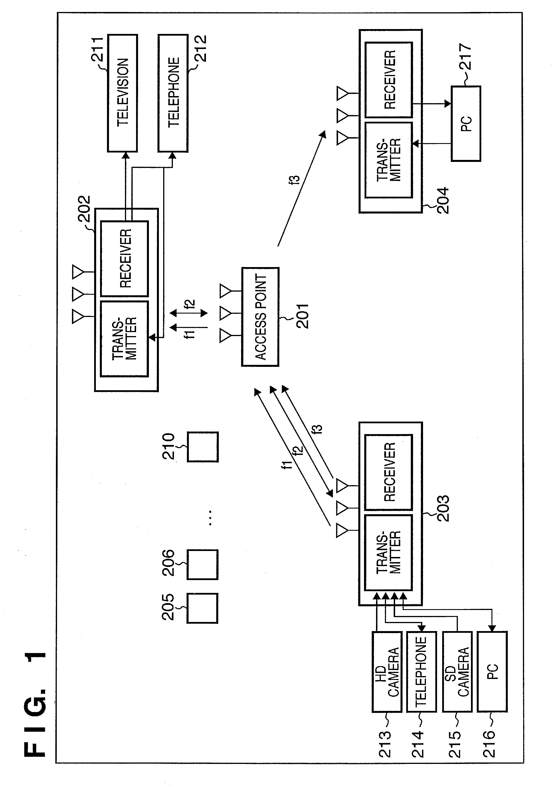
[0024]First, the network configuration of a multiplex transmission system will be described using FIG. 1. FIG. 1 is a diagram showing an exemplary network configuration of the multiplex transmission system. In FIG. 1, reference numeral 201 denotes an access point with wireless LAN functions defined by IEEE 802.11x, which relays wireless communications between wireless terminals. The access point 201 operates like 3×3 switches, where it converts input signals of frequencies f1, f2, and f3 into signals of certain frequencies and outputs the signals. The access point 201 also manages traffic and the bandwidth in the entire network, while wireless terminals obtain transmission rights and perform communications under instructions of the access point 201.

[0025]Reference numerals 202 to 210 denote the wireless terminals respectively, which...


PUM


Abstract

A transmission terminal measures an error rate by periodically transmitting an error rate measuring packet to all transmission channels and all transmission paths. Content to be transmitted is classified, so that a transmission channel of the best transmission quality is assigned to content requiring real-timeness and a wide transmission bandwidth. According to the type of the content, a required communication protocol is selected to perform processing thereof. The transmission bandwidth for the content requiring a wide transmission bandwidth is assigned at a peak rate, while the transmission bandwidth for the content requiring a narrow transmission bandwidth is assigned at an average rate.

Description

TECHNICAL FIELD[0001]The present invention relates to techniques for ensuring transmission quality in a transmission system.BACKGROUND ART[0002]Today, with the start of terrestrial digital broadcasting services, the television system is shifting from SDTV to the finer HDTV. SDTV stands for Standard Definition Television, and HDTV stands for High Definition Television. In addition, opportunities to work with HD video at home are increasing for reasons such as inexpensive general-purpose HD (High Definition) cameras becoming commercially available. There is a need to store the content of digital broadcasting and video taken by HD cameras in a storage device at home to be shared among family members and watch the content and HD video on each member's PC (Personal Computer) at the desired times. Therefore, a network is often established at home for accessing the storage device containing the content and HD video from each member's PC.[0003]For the network at home (home network), a wired...

Claims


Application Information

Patent Timeline
IPC IPC(8): H04N7/173G06F13/00H04N21/4363H04W4/06H04W72/04H04W72/06H04W72/08H04W72/10H04W84/12
CPCH04L1/0018H04L69/14H04L12/2803H04L12/2827H04L12/2834H04L12/2836H04L2001/0093H04L2012/2841H04L2012/2845H04L2012/2849H04N21/2385H04N21/26216H04N21/43637H04N21/631H04N21/64707H04W72/06H04W72/08H04L67/125H04L69/40H04L1/0026H04W72/563H04W72/54
Inventor NAKATA, TORU
Owner CANON KK
Why Eureka
Try Eureka