Microreactor Glass Diaphragm Sensors

a technology of glass diaphragm and micro-reactor, which is applied in the direction of fluid pressure measurement, instruments, transportation and packaging, etc., can solve the problems of difficult formation of complex structures and change of operating pressur

Inactive Publication Date: 2009-03-12
CORNING INC
View PDF17 Cites 17 Cited by
  • Summary
  • Abstract
  • Description
  • Claims
  • Application Information

AI Technical Summary

Benefits of technology

[0013]Another aspect of the present invention relates to a microfluidic device having wall structures comprised of sintered glass frit and a glass, glass-ceramic or ceramic membrane structure sealed by a sintered seal to said wall structures, such that a fluid passage or chamber is defined at least in part by the wall structures and said membrane structure. This allows for changes in pressure within the fluid passage or chamber to cause deflections of the membrane structure, providing for direct measurement of pressure within the device. The microfluidic device may have both floors and walls of sintered frit, or may have only walls of sintered frit, with planar floor-like substrate structures, thicker than the membrane structure defining the vertical boundaries of the internal passages. The device may include multiple fluid passages or chambers each defined at least in part by a membrane structure. Multiple membrane structures may be used in a single device, and one single membrane structure may be used for multiple passages or chambers.

Problems solved by technology

A sudden change in operating pressure could indicate an abnormal processing condition or a leak in the reactor device.
However, the very properties of chemical and physical durability that make glass materials desirable also make them difficult to form into complex structures.

Method used


Image

  • Microreactor Glass Diaphragm Sensors
  • Microreactor Glass Diaphragm Sensors
  • Microreactor Glass Diaphragm Sensors

Examples


Embodiment Construction

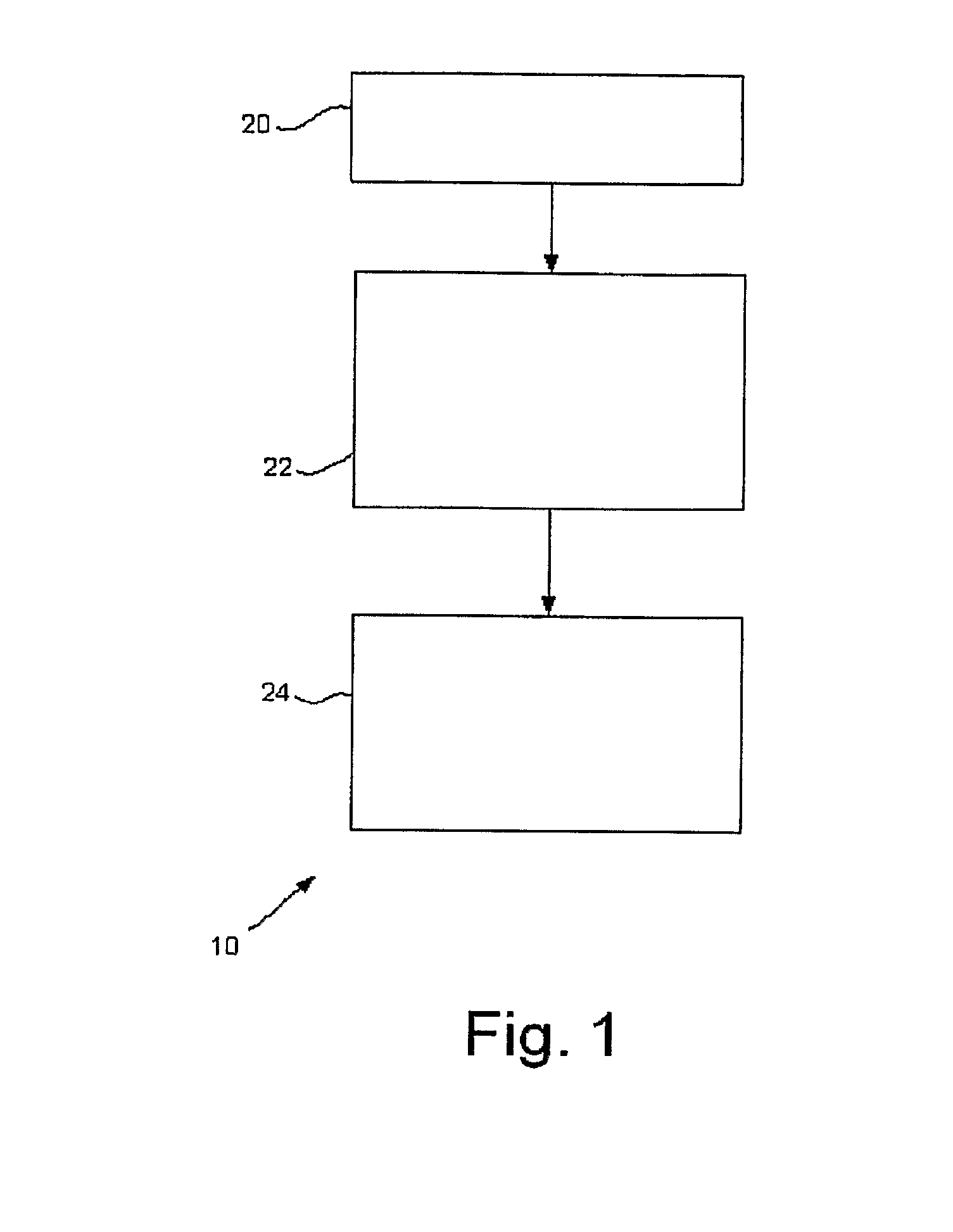
[0023]Reference will now be made in detail to the present preferred embodiment(s) of the invention, examples of which are illustrated in the accompanying drawings. Whenever possible, the same reference numerals will be used throughout the drawings to refer to the same or like parts. One embodiment of a method of the present invention is shown in FIG. 1, and is designated by the reference numeral 10. The method 10 illustrated in FIG. 1 constitutes the basic steps of an embodiment of a method for producing an integrated pressure sensor in a glass-frit based microfluidic device.

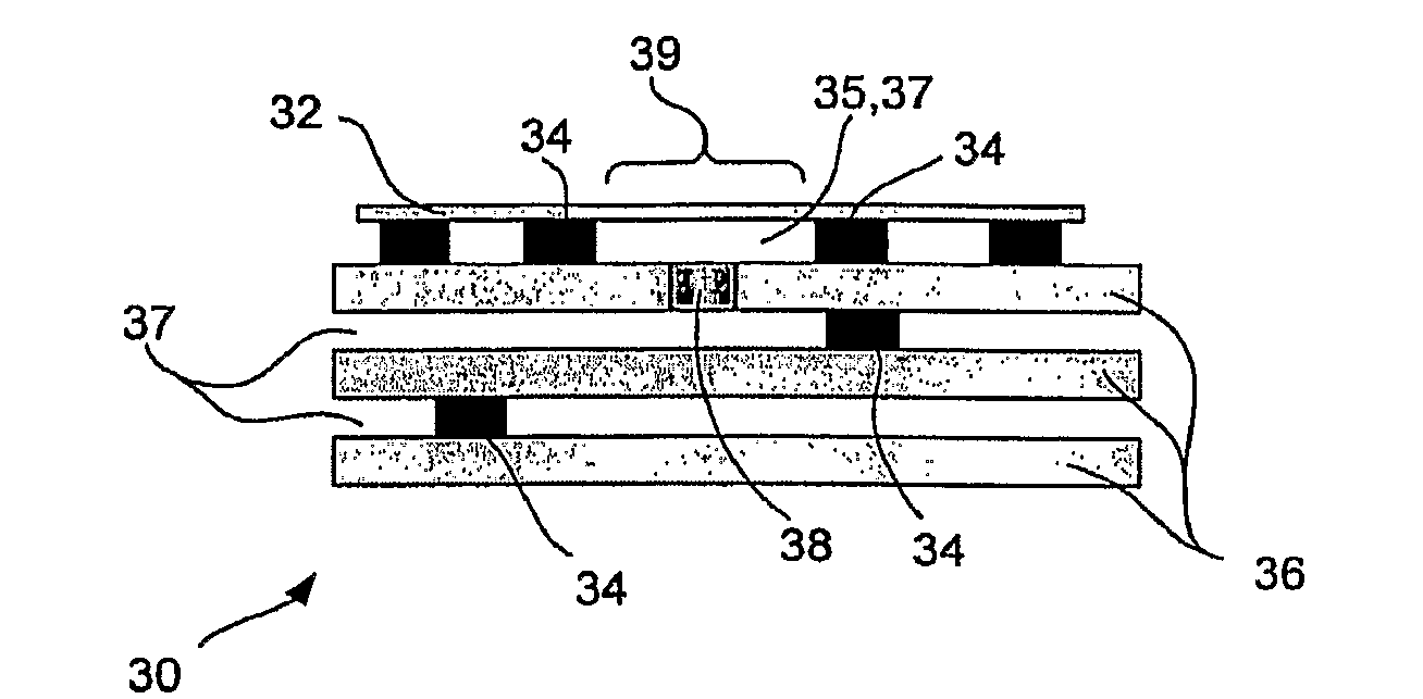
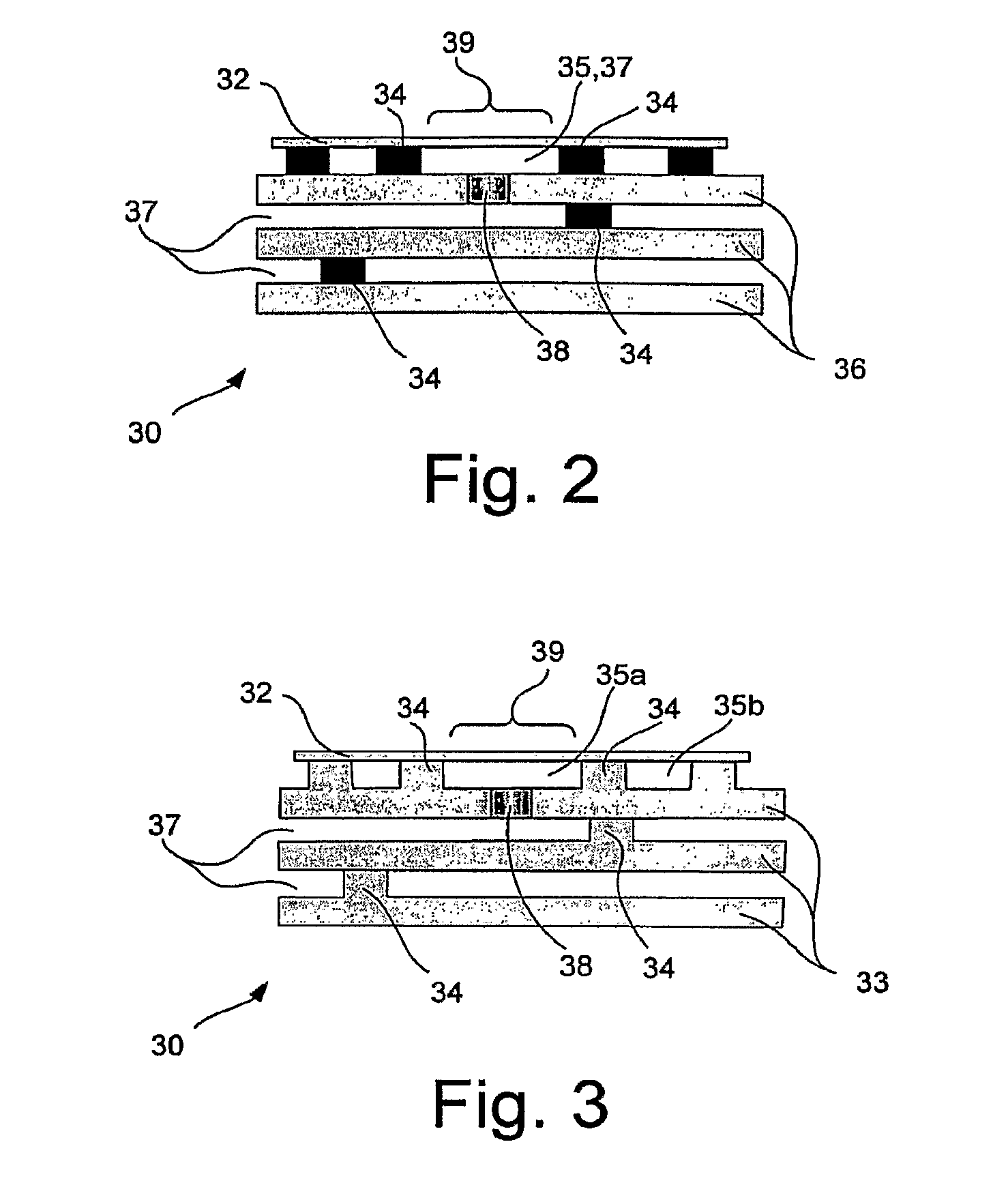
[0024]The method includes step 20, providing a flexible glass, glass-ceramic or ceramic membrane. Glass may be preferred for its transparency, but transparency is not a requirement. Strength and a degree of flexibility are more important. The method also includes step 22, forming microfluidic wall structures defining at least one chamber or passage in which pressure is to be sensed, the wall structures comprisin...


PUM

PropertyMeasurementUnit
thicknessesaaaaaaaaaa

Abstract

Microfluidic devices having wall structures comprised of sintered glass frit and further including a glass, glass-ceramic or ceramic membrane structure sealed by a sintered seal to said wall structures, such that a fluid passage or chamber is defined at least in part by the wall structures and said membrane structure. This allows for changes in pressure within the fluid passage or chamber to cause deflections of the membrane structure, providing for direct measurement of pressure within the device. The microfluidic device may have both floors and walls of sintered frit, or may have only walls of sintered frit, with planar floor-like substrate structures, thicker than the membrane structure defining the vertical boundaries of the internal passages. The device may include multiple fluid passages or chambers each defined at least in part by a membrane structure. Multiple membrane structures may be used in a single device, and one single membrane structure may be used for multiple passages or chamber.

Description

[0001]This application claims priority to U.S. provisional application No. 60 / 755,601 filed Dec. 31, 2005.BACKGROUND OF THE INVENTION[0002]1. Field of the Invention[0003]The present invention relates generally to pressure sensing devices integrated into glass, glass-ceramic, or ceramic microreactor fluidic structures for use in chemical processing, and particularly to glass microreactor pressure sensors that are fabricated using glass, glass-ceramic, or ceramic sheets and glass frit (i.e., glass powder).[0004]2. Technical Background[0005]Microreactor-type chemical processing units have been proposed where fluids (liquids or gases) are guided in etched, molded, drilled or otherwise formed fluid channels in or on planar substrates. Fluid channels are patterned with elementary fluidic structures (e.g., mixers and residence time segments) to form circuits that provide more complex chemical processing functions. Planar substrates can be stacked to extend functionality in a single reactio...

Claims


Application Information

Patent Timeline
Patent Type & Authority Applications(United States)
IPC IPC(8): G01L9/12G01L9/04H01L21/00B81C99/00
CPCB01J19/0093C03C2218/33B01J2219/00824B01J2219/00831B01J2219/00853B01J2219/0086B01J2219/00907B01J2219/00963B01J2219/0097B81B7/02B81B2201/0264B81B2201/051B81B2203/0127B81C2201/019C03C17/04C03C2218/328B01J2219/00783B01D71/04B81C1/00B01F25/00
Inventor DAVIDOVITS, JEROME VIVIENSUTHERLAND, JAMES SCOTT
Owner CORNING INC
Why Eureka
Try Eureka