Compressor tip gap flow control using plasma actuators

a technology of plasma actuators and compressors, which is applied in the direction of machines/engines, water supply installations, liquid fuel engines, etc., can solve the problems of loss of performance, safety and efficiency of axial flow fans and compressors, and the inability to control the flow rate of compressors,

Inactive Publication Date: 2009-03-12
NOTRE DAME DU LAC UNIV OF
View PDF23 Cites 43 Cited by
  • Summary
  • Abstract
  • Description
  • Claims
  • Application Information

AI Technical Summary

Problems solved by technology

The safety and efficiency of axial flow fans and compressor, such as, for instance, gas turbine engines are typically limited, in part, by the performance of the compressors which supply high pressure air for combustion.
Both the efficiency and the stability of the compressors are oftentimes strongly affected by leakage of fluid (e.g., air) through the gap between the rotating compressor blades and the casing.
This leakage flow causes a loss of performance and under certain engine operating conditions can contribute to the onset of rotational stall.
During stall, the compressor may continue to provide compressed air but oftentimes with reduced effectiveness.
Rotational stall may arise when a small proportion of the airfoils experience airfoil stall disrupting the local airflow without destabilizing the compressor.
Local stalls substantially reduce the efficiency of the compressor and

Method used


Image

  • Compressor tip gap flow control using plasma actuators
  • Compressor tip gap flow control using plasma actuators
  • Compressor tip gap flow control using plasma actuators

Examples


Embodiment Construction

[0019]The following description of the disclosed examples is not intended to limit the scope of the disclosure to the precise form or forms detailed herein. Instead the following description is intended to be illustrative of the principles of the disclosure so that others may follow its teachings.

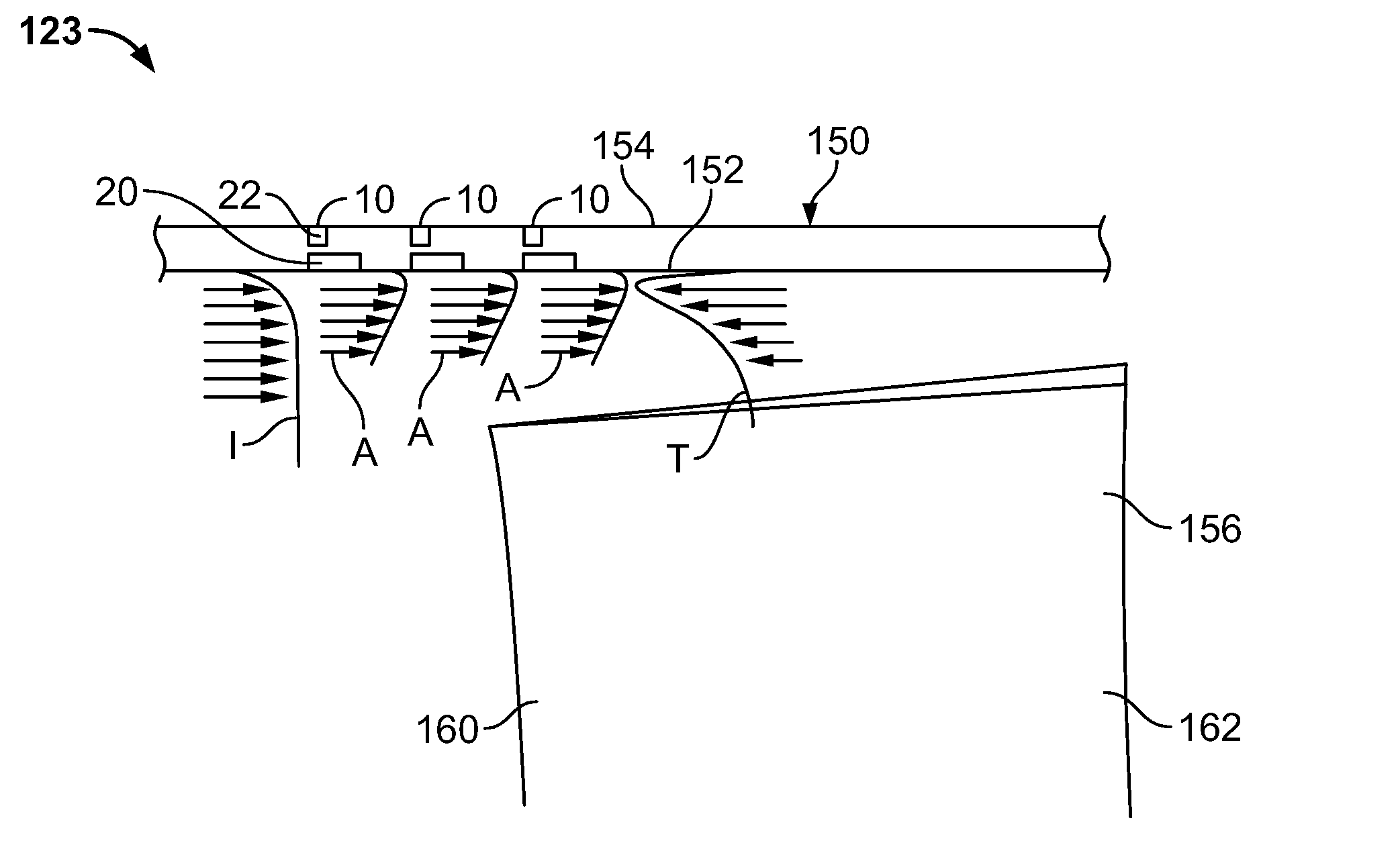
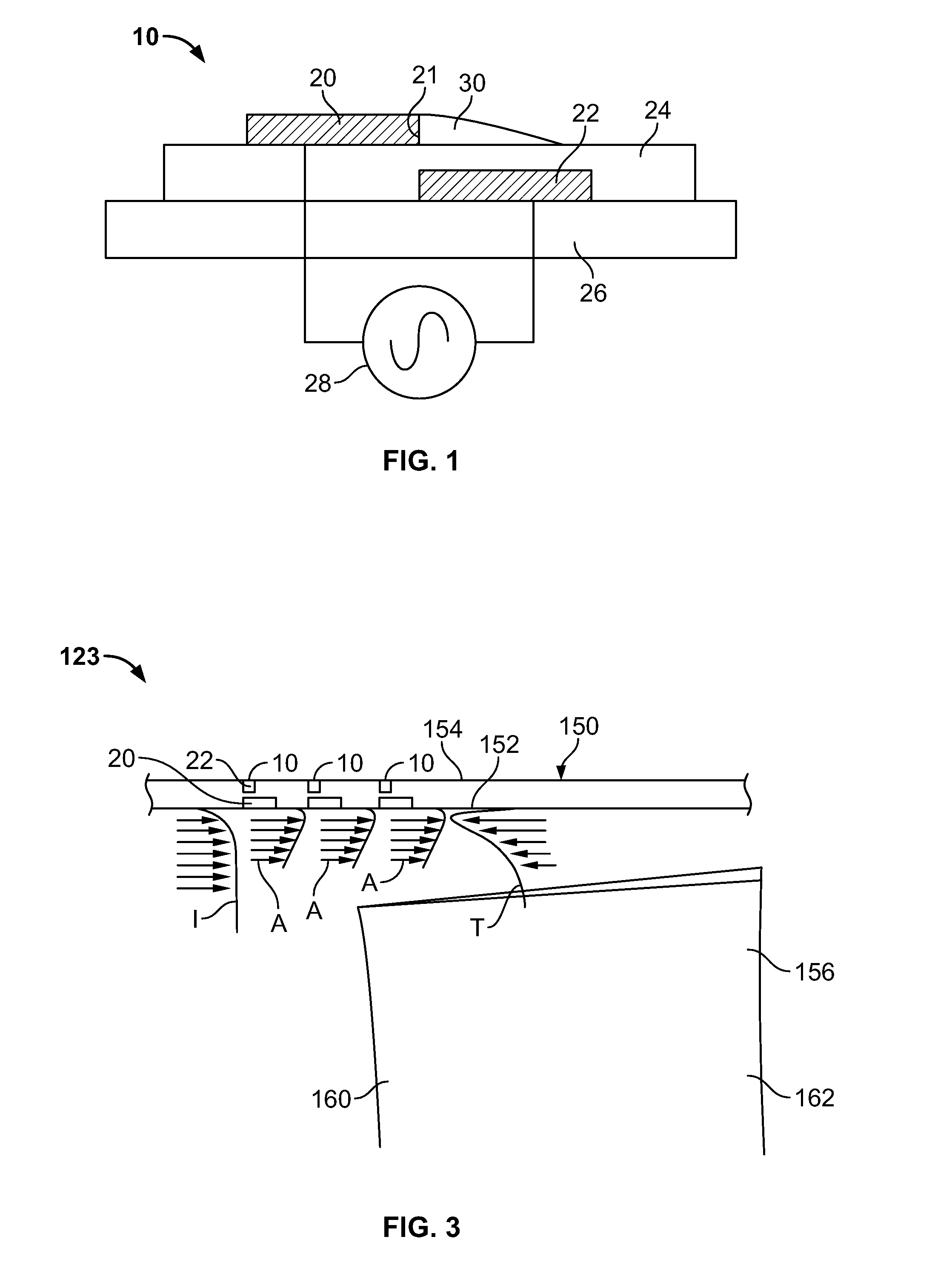
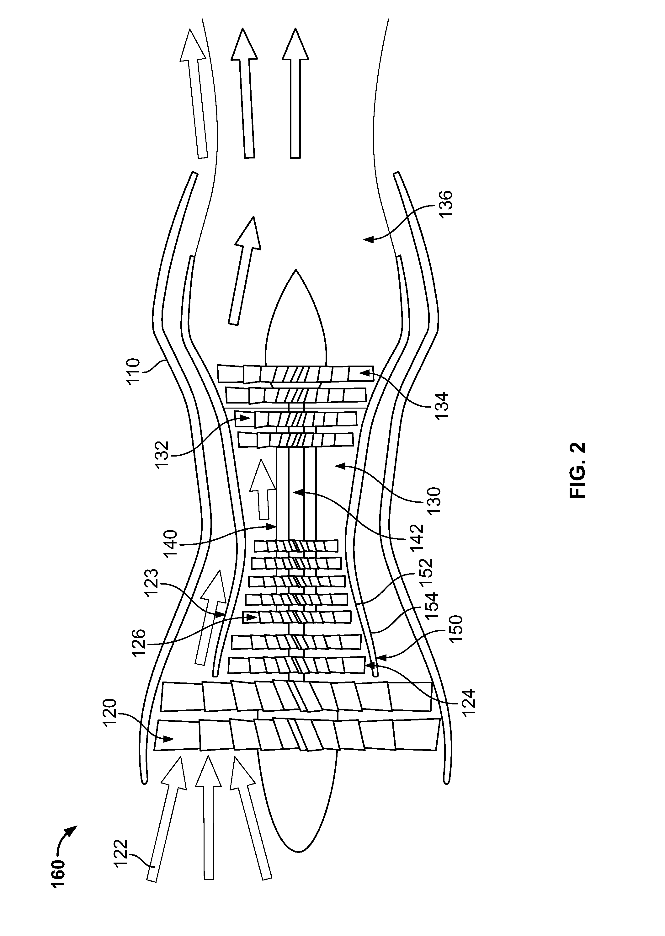
[0020]As described above, passive tip flow control, such as, for example, conventional casing treatment slots, may be provided on the inner surface of a compressor casing around the tips of the compressor blades to attempt to extend the stable flow range over which the compressor may operate. However, passive casing treatments affect the tip flow during all stages of operation, i.e., they are always “on” even when not needed. In the present disclosure, casing surface mounted single dielectric barrier discharge plasma actuators are used to actively control the tip clearance flow. The plasma actuators can be flush mounted into the casing, producing little or no effect on the flow when not in ...


PUM


Abstract

A plasma generator for delaying the onset of rotation stall by tip gap flow control in, for example, an axial flow compressor is disclosed. The tip gap flow control system includes a housing surrounding a rotor of blades and having an inner wall. At least one plasma generating device is coupled to the inner wall of the housing and circumscribes at least a portion of the rotor of blades. A power supply is electrically coupled to the plasma generating device such that when the power supply energizes the plasma generating device, the axial momentum of a fluid flow between the inner wall of the housing and the tips of the rotor of blades in increased in the direction of the fluid flow.

Description

CROSS REFERENCE TO RELATED APPLICATION[0001]This application is a non-provisional application claiming priority from U.S. Provisional Application Ser. No. 60 / 963,017, filed Aug. 2, 2007, entitled “Compressor Tip Gap Flow Control Using Plasma Actuators” and incorporated herein by reference in its entirety.FIELD OF THE DISCLOSURE[0002]The present disclosure relates generally to axial flow devices and more particularly to compressor tip gap flow control using plasma actuators.BACKGROUND OF RELATED ART[0003]The safety and efficiency of axial flow fans and compressor, such as, for instance, gas turbine engines are typically limited, in part, by the performance of the compressors which supply high pressure air for combustion. Both the efficiency and the stability of the compressors are oftentimes strongly affected by leakage of fluid (e.g., air) through the gap between the rotating compressor blades and the casing. This leakage flow causes a loss of performance and under certain engine op...

Claims


Application Information

Patent Timeline
IPC IPC(8): F17D3/00F01D11/08F01D25/00
CPCF01D11/20F04D29/164F05D2270/172F05D2270/17F04D29/681F04D29/687Y10T137/0324
Inventor MORRIS, SCOTT CHRISTOPHERCORKE, THOMAS C.CAMERON, JOSHUA D.
Owner NOTRE DAME DU LAC UNIV OF
Why Eureka
Try Eureka