Liquid cooling jacket

a technology of liquid cooling jacket and cooling jacket, which is applied in the direction of metal-working equipment, basic electric elements, semiconductor devices, etc., can solve the problems of large pressure loss of cooling liquid, increased pump output power, and inability to efficiently cool liquid

Inactive Publication Date: 2009-03-12
NIPPON LIGHT METAL CO LTD
View PDF0 Cites 109 Cited by
  • Summary
  • Abstract
  • Description
  • Claims
  • Application Information

AI Technical Summary

Benefits of technology

[0161]Effects of the liquid cooling jacket J1 are now described.
[0162]The CPU 101 starts to operate and heat up when the personal computer 120 (see FIG. 1) is powered on. Then, the heat of the CPU 101 is transmitted to the bottom 11 of the jacket body 10 via the heat dissipating sheet 102. The heat is further transmitted to the peripheral walls 21b and the partition wall 21c of each of the flat tubes 21 constituting the flat tube bundle. When the personal computer 120 is powered on, the micro pump 122 also starts to operate, and the coolant begins circulating. The coolant flows the first flow passage A1, the second flow passage group B1 (the plurality of the second flow passages B1a) and the third flow passage C1 in order in the liquid cooling jacket J1.
[0163]Then, the heat is exchanged between the peripheral walls 21b and the partition wall 21c of each of the flat tubes 21 and the coolant flowing through the plurality of the second flow passages B1a. The heat of the CPU 101 transmitted to the peripheral walls 21b and the partition wall 21c is further transmitted to the coolant, and thus the coolant receives the heat.
[0164]The coolant having received the heat in each of the second flow passages B1a is collected by the third flow passage C1 and then discharged from the liquid cooling jacket J1 via the outlet 31b and the outlet pipe 33.
[0165]The discharged coolant is supplied to the radiator 121 through the flexible tube 124. The heat of the coolant is dissipated in the radiator 121. The coolant of which temperature is lowered flows into the micro pump 122 through the reserve tank 123 and flexible tube 124, and then supplied to the liquid cooling jacket J1 again.
[0169](3) Dissipation of the heat of the coolant in the radiator 121,

Problems solved by technology

However, a coolant incurs a large pressure loss when a liquid cooling jacket comprises only one flow passage through which the coolant flows as shown in the patent document.
This causes problems that not only a CPU cannot be cooled efficiently, but also the output power of a pump has to be increased to supply the coolant.

Method used


Image

  • Liquid cooling jacket
  • Liquid cooling jacket
  • Liquid cooling jacket

Examples


first embodiment

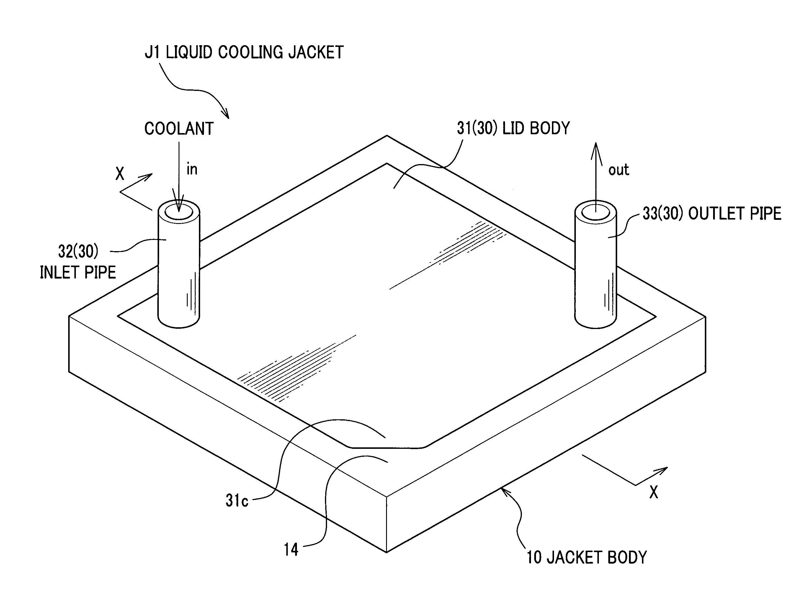
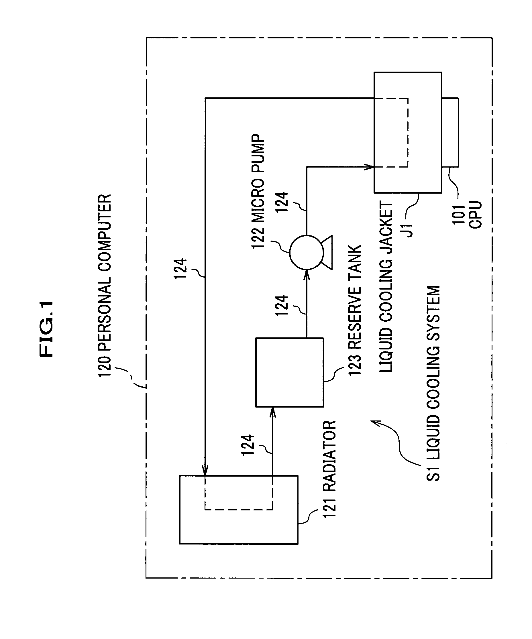
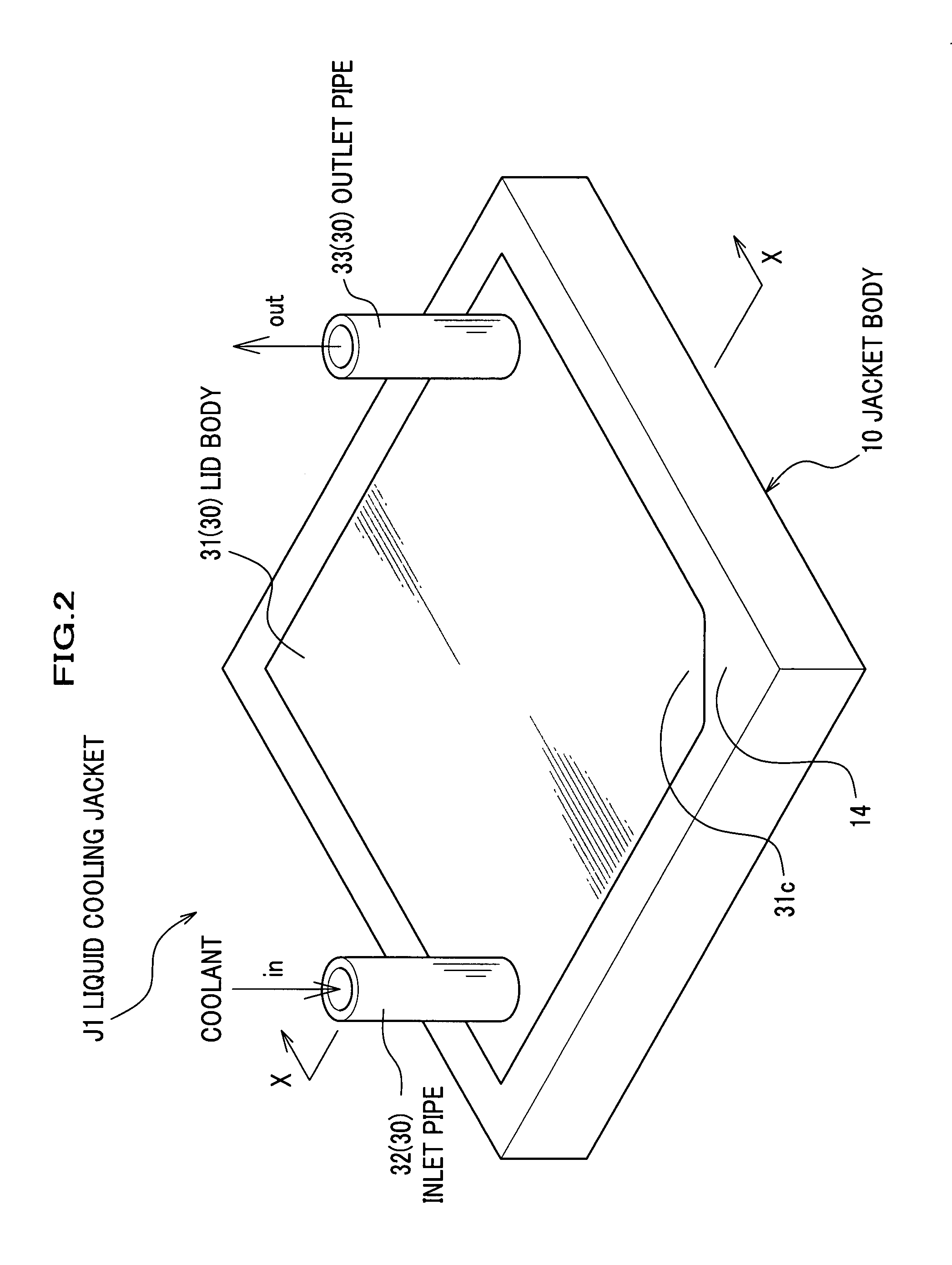
[0139]A liquid cooling system and a liquid cooling jacket according to a first embodiment are now described with reference to FIG. 1 to FIG. 8. FIG. 1 is a block diagram of the liquid cooling system according to the first embodiment. FIG. 2 is a perspective view of a liquid cooling jacket according to the first embodiment. FIG. 3 is a bottom perspective view of the liquid cooling jacket according to the first embodiment. FIG. 4 is a perspective view of the liquid cooling jacket according to the first embodiment, in which a lid unit is omitted. FIG. 5 is a plain view of the liquid cooling jacket according to the first embodiment, in which an inlet pile and an outlet pipe are omitted. FIG. 6 is a cross-sectional view of the liquid cooling jacket according to the first embodiment along a line X-X shown in FIG. 2. FIG. 7 is an exploded perspective view of the liquid cooling jacket according to the first embodiment. FIG. 8 is a graph schematically showing an effect of the liquid cooling ...

second embodiment

[0179]A liquid cooling jacket according to a second embodiment is now described with reference to FIG. 9 and FIG. 10. FIG. 9 is a perspective view of a liquid cooling jacket J2 according to the second embodiment, in which a lid unit is omitted.

FIG. 10 is a cross-sectional view of the liquid cooling jacket J2 according to the second embodiment along a line Y-Y shown in FIG. 9.

[0180]As shown in FIG. 9 and FIG. 10, the liquid cooling jacket J2 according to the second embodiment comprises a flat tube bundle 23 instead of the flat tube bundle 20 of the liquid cooling jacket J1 according to the first embodiment. Although the flat tube bundle 23 is the same as the flat tube bundle 20 in outside dimension, the flat tube bundle 23 is formed by bundling a plurality of laminar flat tubes 24 (three laminar flat tubes in FIG. 9 and FIG. 10). Each of the flat tubes 24 comprises a plurality of inner holes (12 inner holes in FIG. 9 and FIG. 10) inside thereof. Each of the inner holes is a second fl...

third embodiment

[0182]A liquid cooling jacket according to a third embodiment is now described with reference to FIG. 11 and FIG. 12. FIG. 11 is a perspective view of the liquid cooling jacket according to the third embodiment. FIG. 12 is a plain view of the liquid cooling jacket according to the third embodiment.

Configuration of the Liquid Cooling Jacket

[0183]As shown in FIG. 11 and FIG. 12, the liquid cooling jacket J3 according to the third embodiment comprises a lid body 34 on which an inlet 34a and an outlet 34b are disposed in positions different from those of the liquid cooling jacket J1 according to the first embodiment.

[0184]The inlet 34a communicates with substantially center of the space 10a (first flow passage A1). The coolant is supplied to the substantially center of the space 10a. The outlet 34b communicates with substantially center of the space 10c (third flow passage C1). The coolant is discharged from the substantially center of the space 10c. The inlet 34a and outlet 34b are dis...


PUM


Abstract

A liquid cooling jacket (J1) transmits heat generated by a CPU (101) which is installed at a predetermined position to coolant supplied from an external heat transmission fluid supply means and flowing inside of the liquid cooling jacket. The liquid cooling jacket includes a first flow passage (A1) on a side of the heat transmission fluid supply means, a second flow passage group (B1) including a plurality of second flow passages (B1a) branched from the first flow passage (A1), and a third flow passage (C1) installed at downstream side of the plurality of the second flow passages (B1a), and collecting the plurality of the second flow passages (B1a), wherein the CPU (101) mainly dissipates the heat to the second flow passage group (B1).

Description

FIELD OF THE INVENTION[0001]The present invention relates to a liquid cooling jacket for cooling a heating element such as a CPU.[0002]In recent years, cooling a CPU (Central Processing Unit) (a heating element) becomes more and more important because the heating value of a CPU has been increasing with the improvement of the performance of electronic devices such as a personal computer. Conventionally, a heat sink air-cooling fan has been used to cool a CPU. However, the heat sink air cooling fan has problems of fan noise and cooling limit. Thus, a liquid cooling jacket (also referred to as a water cooling jacket or a liquid cooling module) has been receiving attention as a next generation cooling method.[0003]As for such a technique, Japanese Laid-open Patent Application No. 1988-293865 discloses a liquid cooling jacket incorporating a serpentine metallic tube wherein an inlet and an outlet are provided at ends of the metallic tube (see page 2, line 2 in an upper right column to pa...

Claims


Application Information

Patent Timeline
Patent Type & Authority Applications(United States)
IPC IPC(8): F28D15/00
CPCH01L23/473H01L2924/0002H01L2924/00B21J5/068
Inventor KASEZAWA, YOSHIMASAHORI, HISASHIHINO, HARUMICHITANAKA, TSUNEHIKOYOSHIDA, TAKESHI
Owner NIPPON LIGHT METAL CO LTD
Why Eureka
Try Eureka