Centrifugal air classifier

a centrifugal air and classifier technology, applied in the direction of centrifuges, solid separation, gas current separation, etc., can solve the problems of reduction of air or gas per unit mass of powder to be processed, and greatly deterioration of accuracy in so as to improve the accuracy of classification and ratio of collection and no deterioration of accuracy

Active Publication Date: 2009-03-12
TAIHEIYO CEMENT CORP
View PDF13 Cites 14 Cited by
  • Summary
  • Abstract
  • Description
  • Claims
  • Application Information

AI Technical Summary

Benefits of technology

[0009]In view of the above, an object of the present invention is to achieve a required classification performance with the flow rate of the air or gas lower than the conventional flow rate.
[0014]Further, the inventor of the present invention paid attention to the height of the rotor. Regarding improvement in accuracy of classification and ratio of collection, there is not any established quantitative theory with respect to the height but only two opposite qualitative opinions. The first opinion is that “the height of the rotor should be sufficiently high in order to give all particles enough opportunities of classification”. On the other hand, the second opinion is that “the height of the rotor should be low in order to quickly complete classification for the purpose of preventing an unnecessary size of particles from being mixed in the classification”.
[0029]Designing the rotor and the rotor blades to be smaller than S1 and S2 has a sufficient probability of deterioration in accuracy in classification and ratio of collection of products. On the other hand, designing the above to be larger than S1 and S2 causes no problem of the accuracy in classification and the ratio of collection but causes increase in the amount of investment in plant and equipment and running costs.
[0034]The inventor of the present invention concluded that the reason of the above was that the powder supplied to the classifier entered from the outer circumferential part of the dispersion plate in the upper part of the rotor into the classification space (between the guide vane and the rotor blades) to undergo a classification operation, and at that time, the concentration of the powder per a unit space was lower in the case that the powder entered evenly and as widely as possible from the whole outer circumference of the dispersion plate than the case that the powder entered intensively from any one place of the outer circumference part of the dispersion plate, and thereby, the dispersion of the powder was accelerated, so that the classification became close to the desirable one.
[0035]That is, it can be considered that setting the height of the rotor in accordance with the invention causes no deterioration in accuracy in classification and ratio of collection even in the case that an unvigorous classification that occurs below the point CP (the border point) is omitted, since properly providing the powder inlet causes improvement in accuracy in classification and ratio of collection.

Problems solved by technology

Generally, the accuracy in classification is greatly deteriorated when the flow rate of air or gas per unit mass of a powder to be processed is decreased.
However, when the flow rate of the air or gas is decreased with a current centrifugal classifier without properly changing a structure of the classifier, the accuracy in classification is greatly deteriorated as described above, and thereby, quality (function) of a powder product and a ratio of collection of a product powder (on any one of the fine powder side and the coarse powder side) are deteriorated.
This causes a tendency of deterioration, as a result.

Method used


Image

  • Centrifugal air classifier
  • Centrifugal air classifier
  • Centrifugal air classifier

Examples


embodiment 1

[0058]A first embodiment of the present invention will be described.

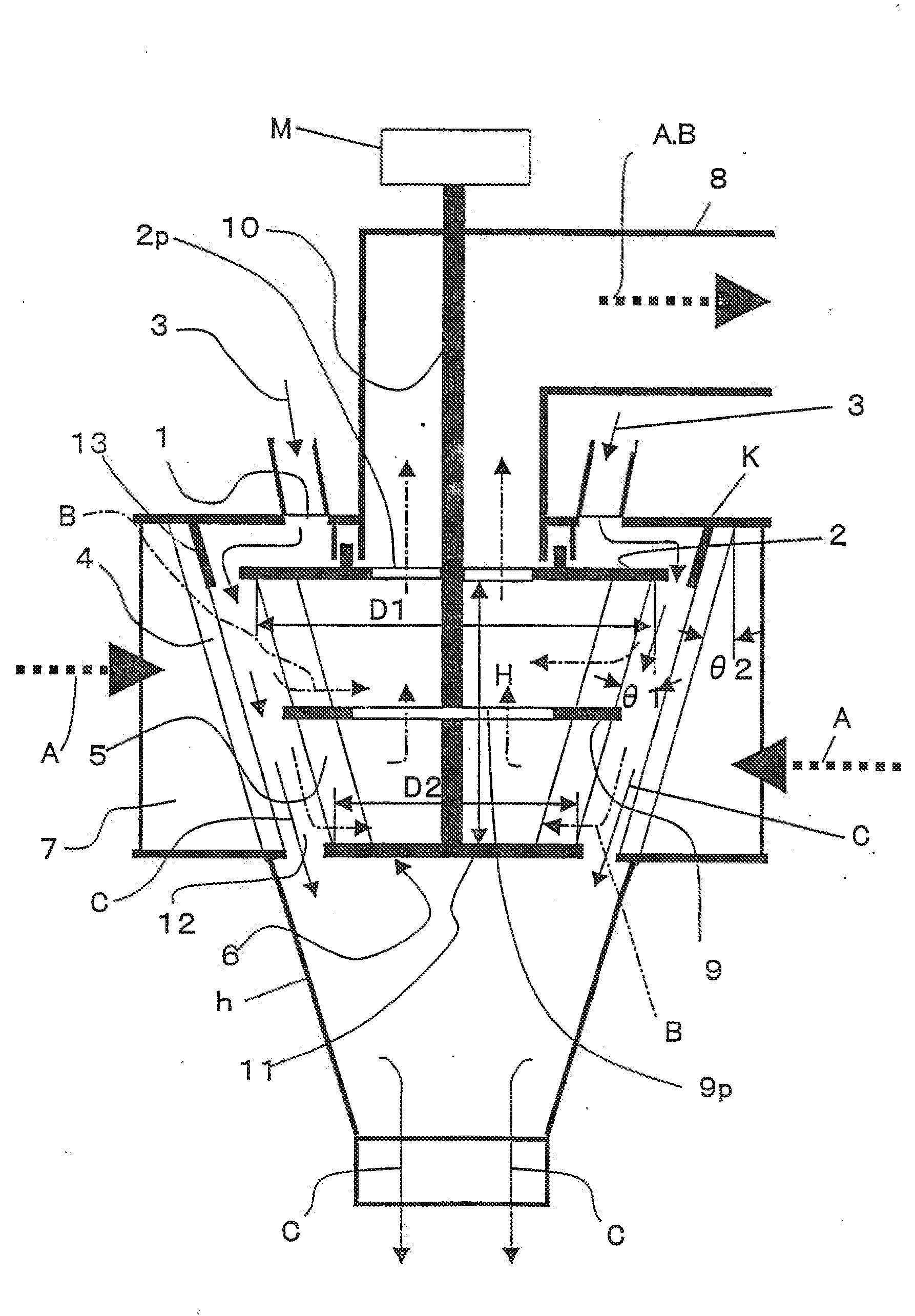
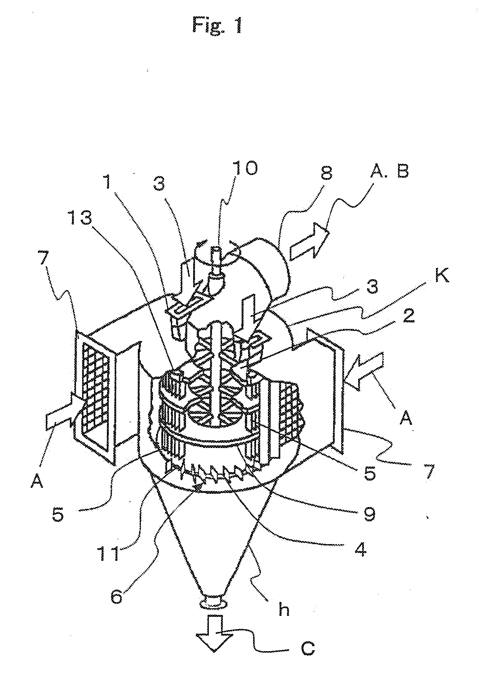
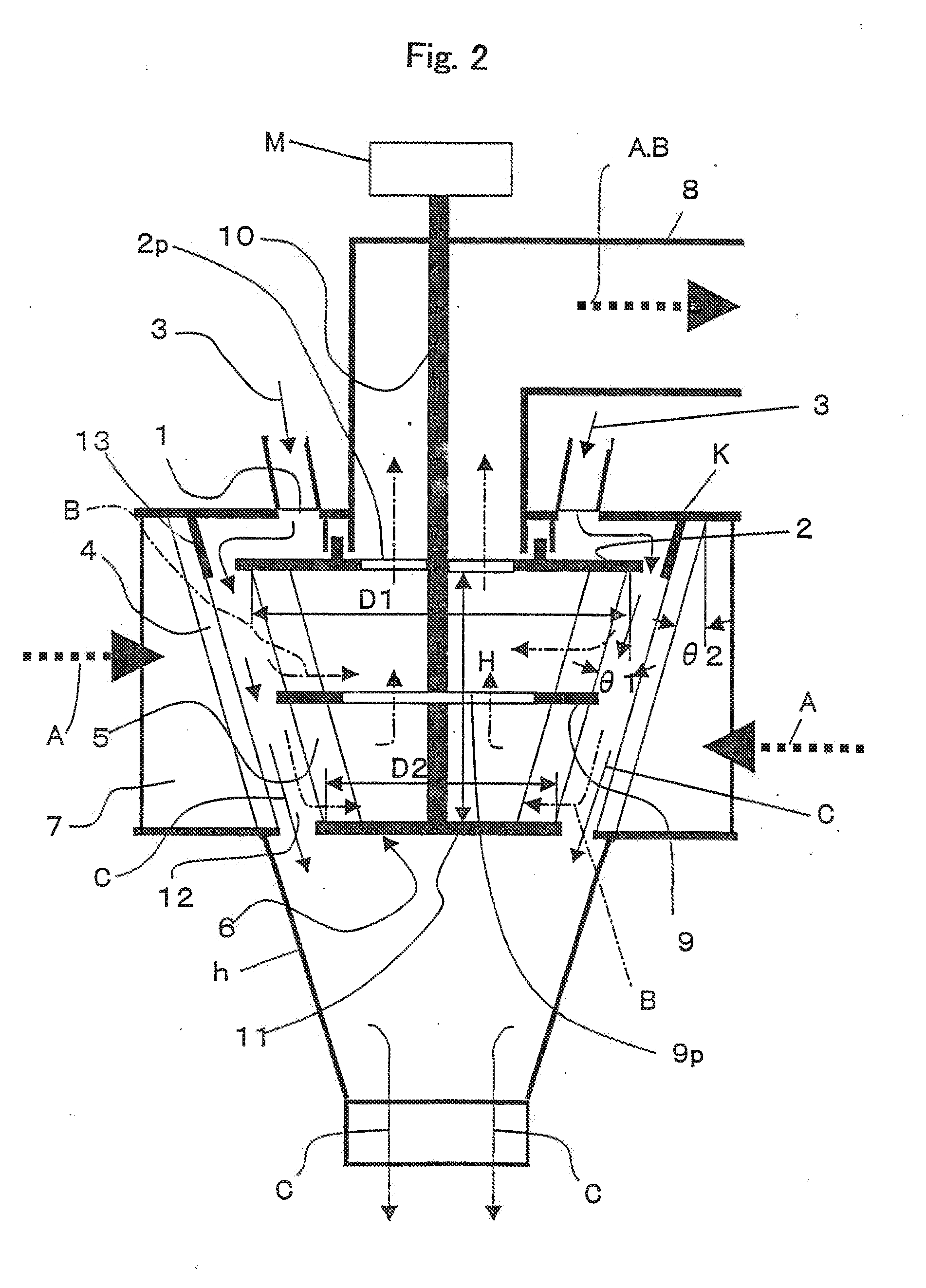
[0059]A centrifugal air classifier shown in FIGS. 1 and 2 is a typical classifier having been conventionally used and being in actual operation in world cement plants widely. As described above, the classifier comprises a casing k whose lower part is formed into a cone-shaped hopper h, an air inlet 7 provided in the tangent direction to a cylindrical part of the casing, a fine powder outlet 8 mounted to the top of the casing, a rotor rotational shaft 10 mounted to the almost center in the cylindrical part of the casing, a rotational plate 11 mounted to the rotational shaft 10, a dispersion plate 2 mounted to a place where a powder raw material 3 falls from the powder inlet 1, a plurality of rotor blades 5 whose one ends are fixed to the rotational plate 11 and whose other ends are fixed to the dispersion plate 2, a horizontal partition plate 9 mounted to the rotor blades 5 for partitioning a classification chamber f...

embodiment 2

[0071]Embodiment 2 shows a case that a comparatively large-sized classifier according to the present invention is newly provided instead of alteration. A centrifugal air classifier of the same kind as that of Embodiment 1 is redesigned on the basis of the invention. As a subject for comparison in performance, used is a centrifugal classifier of the same kind as that of Embodiment 1, the classifier having the same production scale and being in operation adjacently in the same cement plant, wherein the technique of the invention is not applied to the classifier. The data is shown in Table 3.

[0072]In Table 3, S1 (in meters squared) is 9.00 in the present embodiment and 12.86 in the subject for comparison, S2 (in meters squared) is 7.75 in the present embodiment and 11.07 in the subject for comparison and D in meters) is 2.64 in the present embodiment and 2.64 in the subject for comparison. In any one of the cases of ordinal cement and high-early-strength cement, the setting was same.

TA...


PUM


Abstract

A centrifugal air classifier, in which a relation between an area S1 of a side surface of a cylinder or a truncated cone circumscribed about the rotor blades, an axis of the cylinder or a truncated cone being the rotor rotational shaft, and a calculation average value D of a diameter of a circle orthogonal to the rotor rotational shaft and circumscribed about the rotor blades is S1 / D2=0.9 to 1.6, and with the S1, a relation between a cross sectional area S2 of inflow of the air for classification and the D is S2 / D2=0.8 to 1.4.

Description

FIELD OF THE INVENTION[0001]The present invention relates to a centrifugal air classifier for sorting a powder-shaped raw material into a coarse powder and a fine powder. Removing by means of a classifier an unnecessary size of particles in a powder obtained in a crushing operation or the like to obtain a necessary size of particles is regarded as important not only in the cement industry but also in many fields such as various kinds of mining and manufacturing industries, food industry, pharmaceutical industry and various kinds of chemical industries for the purpose of obtaining a function required to the powder and improving in function.[0002]Among the above, in the various kinds of mining and manufacturing industries, the cement industry, the iron industry and the like, an extremely large quantity of powder subject to classification causes investment in plant and equipment and the running costs (such as expenses for electric energy) to be increased, so that decrease in cost is ea...

Claims


Application Information

Patent Timeline
Patent Type & Authority Applications(United States)
IPC IPC(8): B07B7/083B04B7/08
CPCB07B7/083B04B7/08
Inventor ITO, MITSUHIRO
Owner TAIHEIYO CEMENT CORP
Why Eureka
Try Eureka