
Fuel injection system

a fuel injection and system technology, applied in the direction of marine propulsion, vessel construction, aircraft navigation control, etc., can solve the problem of insufficient uniform distribution of fuel, and achieve the effect of optimizing the homogenization of fuel

Inactive Publication Date: 2009-03-12
ROBERT BOSCH GMBH
View PDF5 Cites 3 Cited by
  • Summary
  • Abstract
  • Description
  • Claims
  • Application Information

AI Technical Summary

Benefits of technology

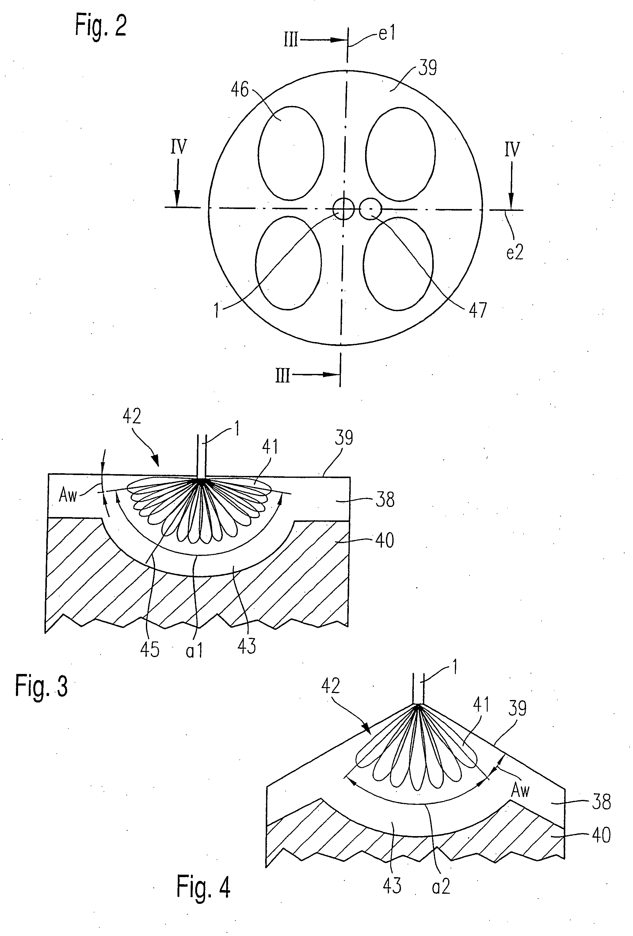
[0004]The fuel injection system according to the present invention has the advantage over the prior art that the distribution of fuel in combustion chambers, without using rotationally symmetric combustion chamber tops, is able to be implemented in a more uniform manner.
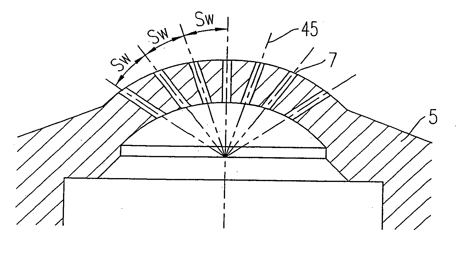
[0005]The spray cloud is advantageously formed in such a way that a constant clearance angle between combustion chamber top and spray cloud results in the circumferential extension of the spray cloud, the spray cloud being embodied as “shower head spray” which evenly distributes a multitude of fuel jets into the combustion chamber. This makes it possible to improve the distribution and combustion of the fuel.

Problems solved by technology

A particular disadvantage of the fuel injection system known from the aforementioned published German patent document is that, in combustion chambers having a combustion-chamber top that is not rotationally symmetrical, the fuel is distributed with insufficient uniformity.

Method used


Image

  • Fuel injection system
  • Fuel injection system
  • Fuel injection system

Examples


Embodiment Construction

[0022]In the following, example embodiments of the present invention are described, with identical components having been provided with identical reference numerals in the figures.

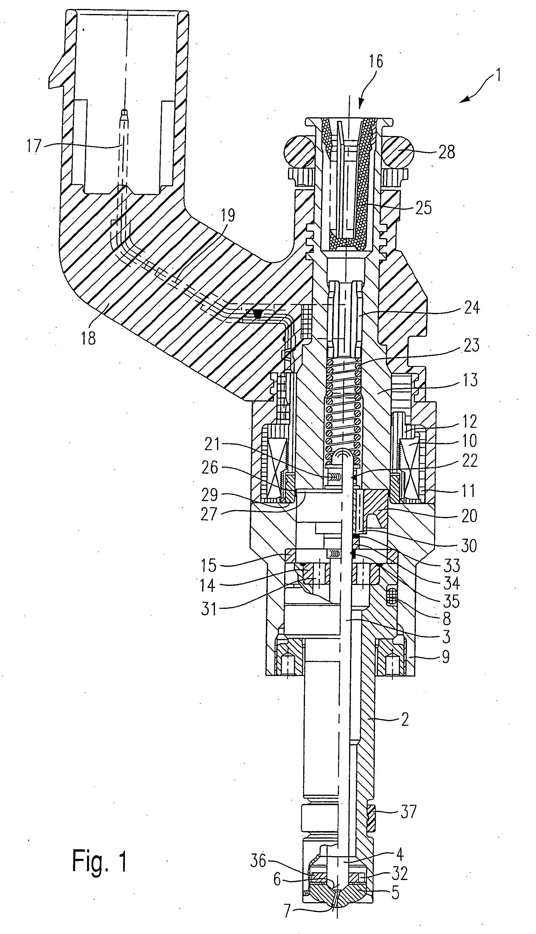
[0023]Before providing a detailed description of example embodiments according to the present invention, in order to provide a better understanding of the present invention, a generic fuel injector shall be first explained briefly with reference to FIG. 1.

[0024]An example of a generic fuel injector 1, shown in FIG. 1, is for fuel-injection systems of mixture-compressing internal combustion engines having externally supplied ignition. Fuel injector 1 is suited, in particular, for the direct injection of fuel into a combustion chamber (not shown) of an internal combustion engine.

[0025]Fuel injector 1 includes of a nozzle body 2 in which a valve needle 3 is positioned. Valve needle 3 has a valve-closure member 4 on its discharge side, which cooperates with a valve-seat surface 6 disposed on a valve-seat membe...


PUM


Abstract

A fuel-injection system for direct injection of fuel into a combustion chamber through a combustion-chamber top arranged opposite a piston has a fuel injector which includes an actuable valve-closure member. The valve-closure member cooperates with a valve-seat surface to form a sealing seat. A multitude of spray-discharge orifices generates a spray cloud, each spray-discharge orifice generating a fuel jet, and the multitude of fuel jets generating the spray cloud in the combustion chamber. A first opening angle of the spray cloud in a first plane is greater than a second opening angle in a second plane extending perpendicular to the first plane.

Description

FIELD OF THE INVENTION[0001]The present invention relates to a fuel-injection system having a plurality of spray-discharge orifices.BACKGROUND INFORMATION[0002]Published German Patent document DE 101 03 050 describes a fuel injector having a plurality of spray-discharge orifices. The spray-discharge orifices are disposed in such a way that a fuel envelope which is as uniform as possible towards all sides and which has an identical opening angle toward all sides is generated in the combustion chamber during the injection process.[0003]A particular disadvantage of the fuel injection system known from the aforementioned published German patent document is that, in combustion chambers having a combustion-chamber top that is not rotationally symmetrical, the fuel is distributed with insufficient uniformity.SUMMARY[0004]The fuel injection system according to the present invention has the advantage over the prior art that the distribution of fuel in combustion chambers, without using rotat...

Claims


Application Information

Patent Timeline
Patent Type & Authority Applications(United States)
IPC IPC(8): B63H11/10F02B23/06F02B23/10F02M61/14F02M61/18
CPCF02B23/0669F02B23/0696F02B23/101F02B23/104Y02T10/125F02B2023/103F02M61/14F02M61/182F02M61/1826F02B2023/102Y02T10/12
Inventor VOGEL, MANFREDHERDEN, WERNERECKER, RAINER
Owner ROBERT BOSCH GMBH
Learn More