Power switch device

a power switch and power button technology, applied in the direction of instruments, computer control, pulse technique, etc., can solve the problems of unfavorable user operation, unfavorable user operation, and increased cost of the casing structure, so as to prevent accidental touch of the power button and prevent unexpected power

Inactive Publication Date: 2009-03-12
INVENTEC CORP
View PDF4 Cites 8 Cited by
  • Summary
  • Abstract
  • Description
  • Claims
  • Application Information

AI Technical Summary

Benefits of technology

[0007]Accordingly, an objective of the present invention is to provide a power switch device that can

Problems solved by technology

However, as a power button is protrudingly disposed at front panel of a server, the power button may be accidentally touched, thereby leading to unexpected shutdown of the server.
The above-described complicated processes are not convenient for users to conduct ope

Method used


Image

  • Power switch device
  • Power switch device
  • Power switch device

Examples


first embodiment

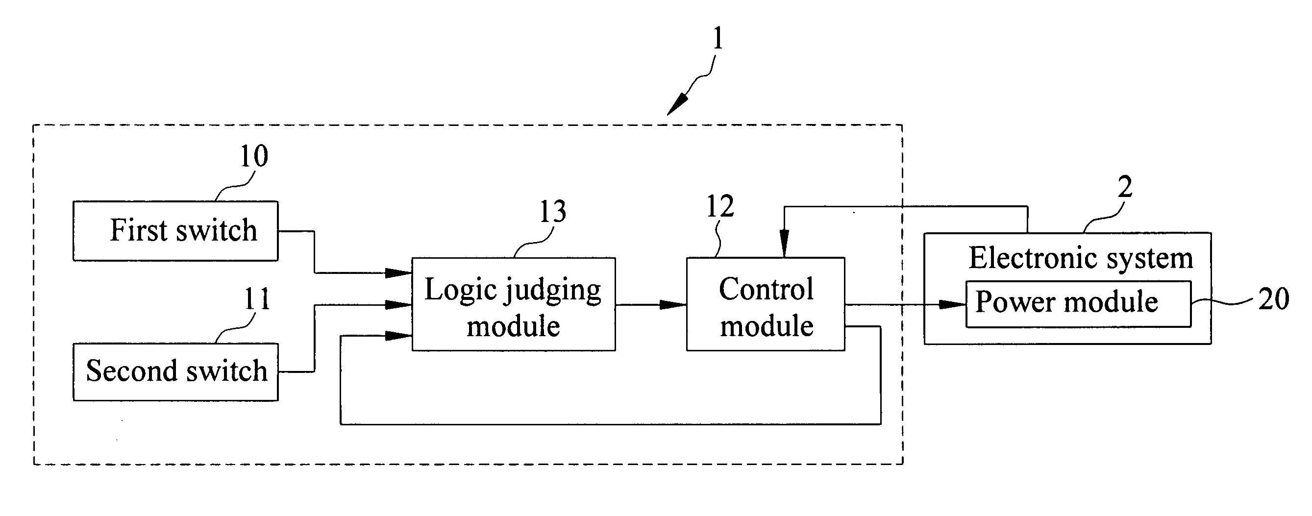
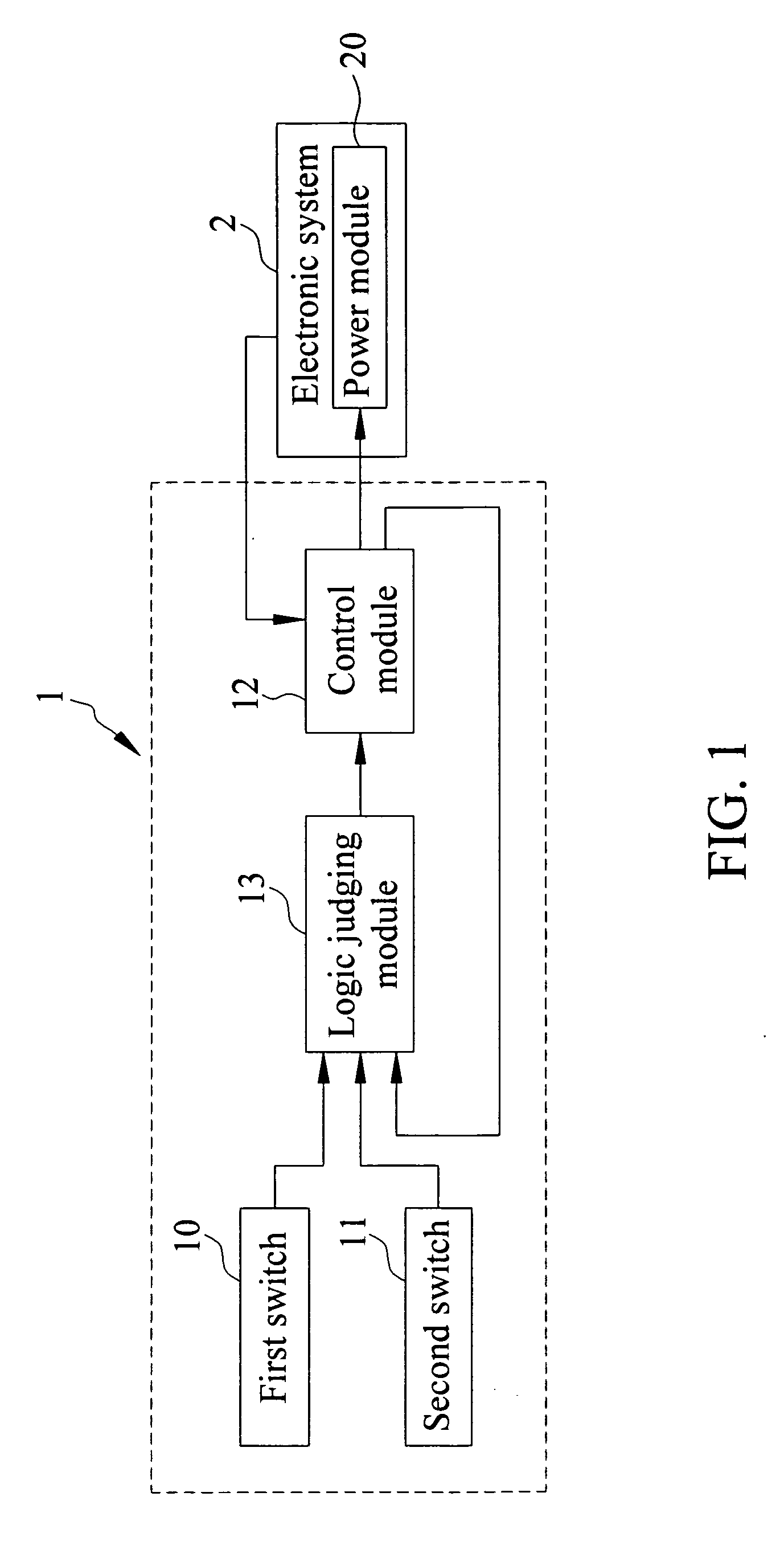
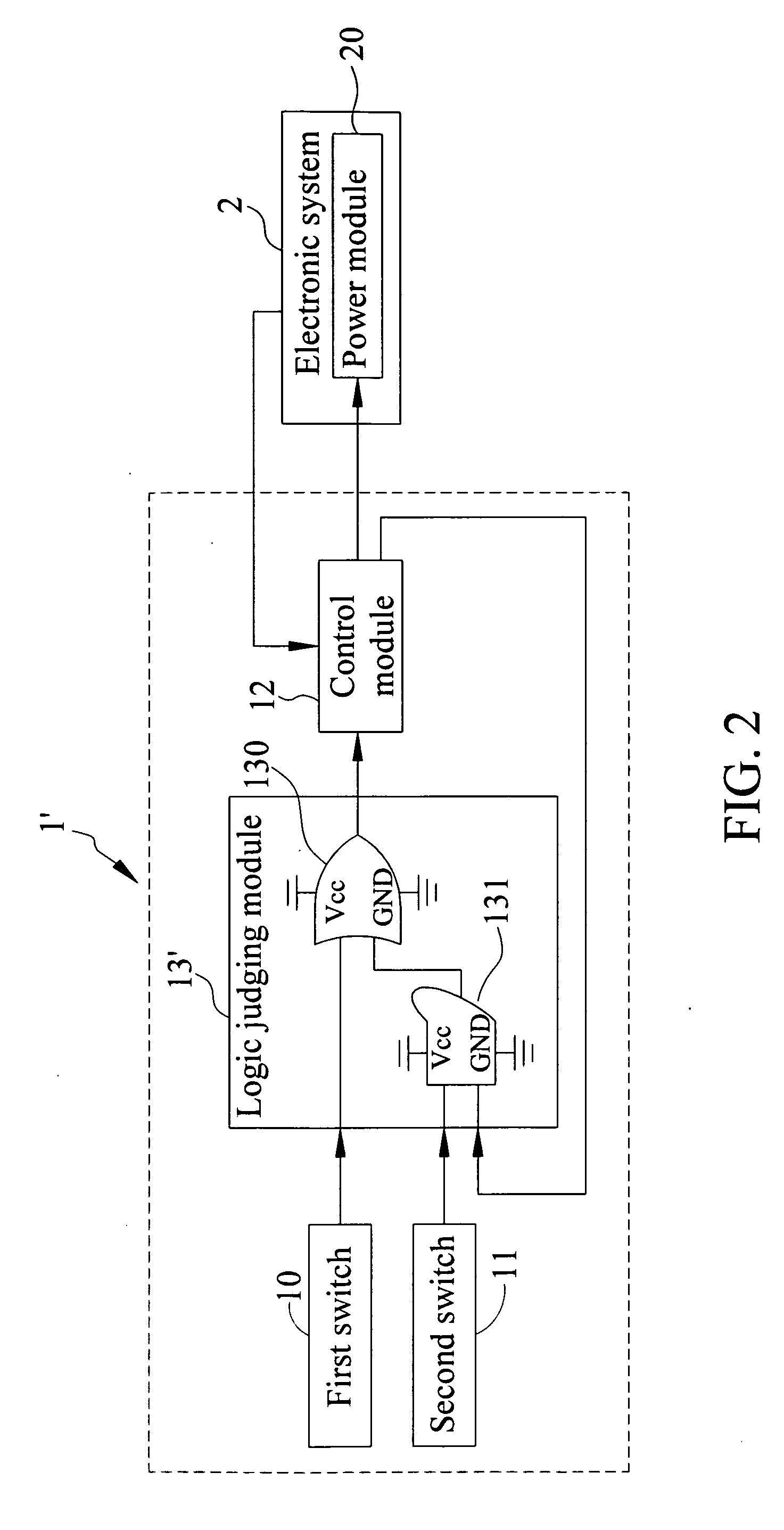
[0019]FIG. 2 is a schematic view showing a power switch device according to the present invention. The power switch device of FIG. 2 has a substantially same structure as that of FIG. 1 except the logic judging module 13′ thereof. In the present embodiment, the logic judging module 13′ is a logic circuit including an OR gate 130 and an AND gate 131. In light of the result of the logic algorithm processing performed by the logic judging module 13′, the power module 20 of the electronic system 2 is controlled to be on or off.

[0020]More specifically, the power module 20 of the present embodiment switches on or off the power supply after receiving a low-level signal (that is, the control signal is ‘0’) from the control module 12. That is, the low-level signal is an activation signal for power supply of the power module 20. The control module 12 transmits a signal (an on or off signal) corresponding to the on or off state of the electronic system 2 back to the logic judging module 13. Fo...

second embodiment

[0025]FIG. 3 is a schematic view showing a power switch device according to the present invention. The power switch device of FIG. 3 has a substantially same structure as that of FIGS. 1 and 2 except the logic judging module 13″ thereof. In the present embodiment, the logic judging module 13″ includes a programmable logic unit 132, which can be such as a complex programmable logic device (CPLD) or a field-programmable gate array (FPGA). In other words, the power module 20 is controlled through a programmable method. FIG. 4 shows input and output signals of a complex programmable logic device that is used as a programmable logic unit 132. The program of the complex programmable logic device is shown as follows.

module PWRBTN(  SYS_SWITCH1_N,  SYS_SWITCH2_N,  SB_S4— N,  PWR_BTN— N);  input SYS_SWITCH1_N;  input SYS_SWITCH2_N;  input SB_S4— N;  output PWR_BTN_N;  reg PWR_BTN_N; assign PWR_BTN_N = SYS_SWITCH1_N | (SYS_SWITCH2_N & SB_S4_N);endmodule

in which, ‘|’ represents logic OR, ‘&’ r...


PUM


Abstract

The invention provides a power switch device for electronic systems equipped having a power module. The power switch device includes a first switch for activating a first signal, a second switch for activating a second signal, a logic judging module for receiving the first and second signals for logic algorithm processing, and a control module electrically connected to the electronic system and the logic judging module. The control module is adapted to generate and transmit on and off signals of the electronic system to the logic judging module. Further, the control module controls switching on the power module according to the off signal and the logic algorithm processing based on the first signal, and also controls switching off the power module according to the on signal and the logic algorithm processing based on the first and second signals.

Description

BACKGROUND OF THE INVENTION[0001]1. Field of the Invention[0002]The present invention relates generally to a power switch device, and more particularly to a power switch device that switch on / off a power module of an electronic system according to logic judging result.[0003]2. Description of Related Art[0004]An enterprise server normally operates 24 hours a day. However, as a power button is protrudingly disposed at front panel of a server, the power button may be accidentally touched, thereby leading to unexpected shutdown of the server. To reduce such a risk, the power button can be disabled in BIOS, but functions of other buttons disposed at the front panel of the server are also disabled at the same time. Under some special circumstances where a server needs to be shut down and then restarted, the server must be restarted so as to enable the power button in BIOS. Then, the server can be shut down and started again by pressing the power button. The above-described complicated pro...

Claims


Application Information

Patent Timeline
IPC IPC(8): G05B15/02
CPCH03K19/00392H03K17/00
Inventor LUO, ZI-GUIJI, HAI-YICHEN, CHIH-FENG
Owner INVENTEC CORP
Why Eureka
Try Eureka