Electric motor apparatus capable of reducing friction

a technology of electric motors and motor components, which is applied in the direction of positive displacement liquid engines, pumps, machines/engines, etc., can solve the problems of not being able to meet user requirements, affecting the normal operation of the rotor, and still having a conventional structur

Inactive Publication Date: 2009-03-12
TEK CHAIN TECH
View PDF15 Cites 2 Cited by
  • Summary
  • Abstract
  • Description
  • Claims
  • Application Information

AI Technical Summary

Benefits of technology

[0009]Therefore, it is a primary objective of the present invention to provide an electric motor apparatus applied to an electric motor for effectively reducing the friction produced between an axle and a bearing, decreasing the noise and wearing of the axle when the electric motor is rotated, and further improving the life expectancy and efficiency of a fan.
[0010]Another objective of the present invention is to provide an electric motor apparatus that installs a stator and a rotor thereon, wherein the stator has an axle sleeve, an embedded groove extended inward and disposed at an internal side of an opening at a free end of the axle sleeve, and the axle sleeve is sheathed with a bearing; and the rotor has an axle sheathed into the bearing, and a latch disposed at an internal side of the rotor and corresponding to the embedded groove. With the embedded groove and the latch, the stator and the rotor can be latched with each other easily.
[0013]Another objective of the present invention is to build a slot along the axial direction and at the periphery of the embedded groove, such that the slot can provide an elasticity of expanding and contracting the embedded groove.

Problems solved by technology

However, the conventional structure still has the following issues in its practical applications.
As a result, the normal operations of the rotor will be affected, and such arrangement cannot meet user requirements.
If the thickness is insufficient to meet the expected magnetism requirement, then it is necessary to increase the thickness of the magnetic pressing member, and thus a higher cost will be incurred.
With the assembly and structural configuration of the magnet, the magnetic metal member 402 can transmit a magnetic force of the magnetic circular body 401 to obtain a magnetic attraction, but such arrangement will increase the area of frictions and the manufacturing cost.

Method used


Image

  • Electric motor apparatus capable of reducing friction
  • Electric motor apparatus capable of reducing friction
  • Electric motor apparatus capable of reducing friction

Examples


Embodiment Construction

[0022]To make it easier for our examiner to understand the technical characteristics of the invention, we use preferred embodiments together with the attached drawings for the detailed description of the invention.

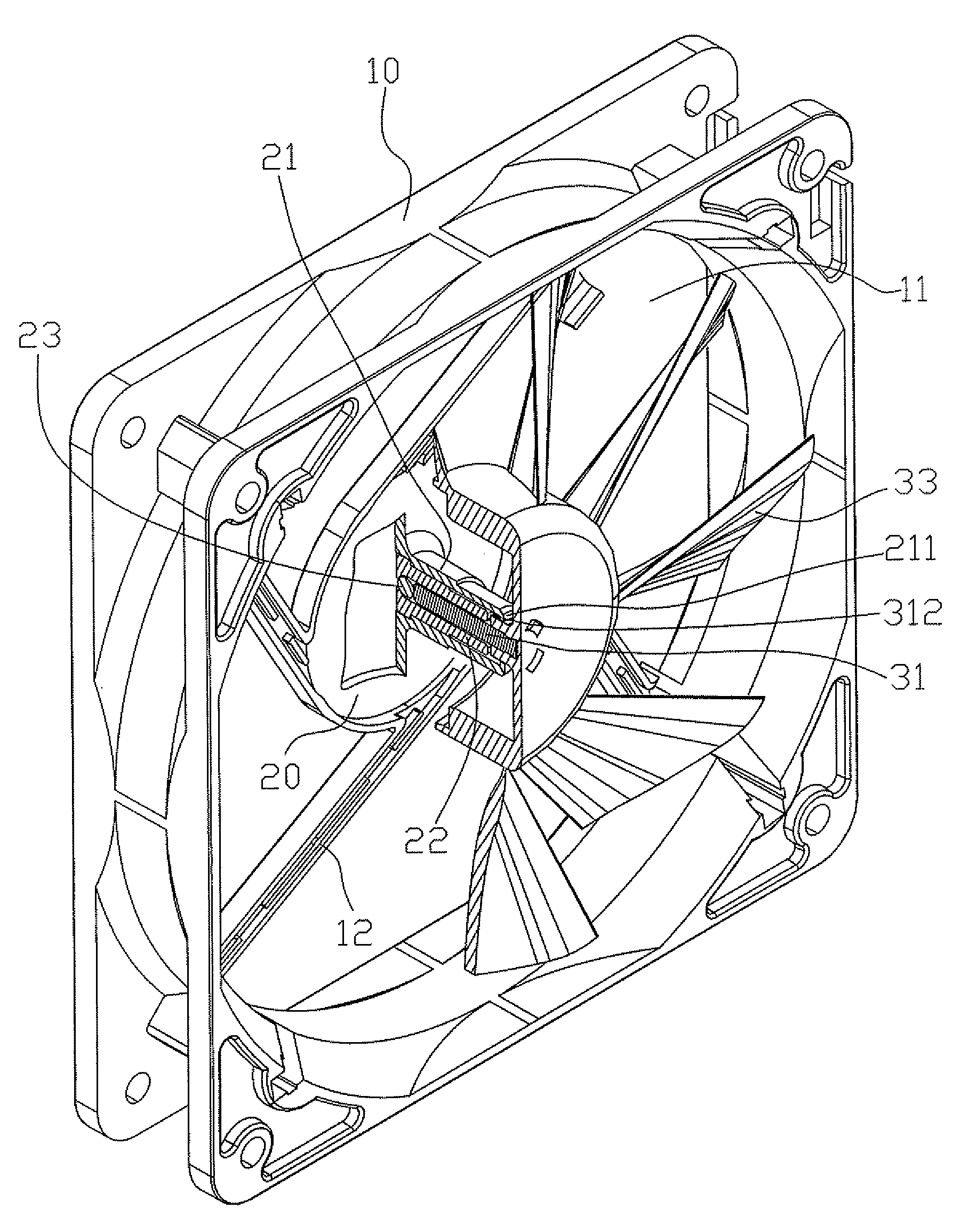
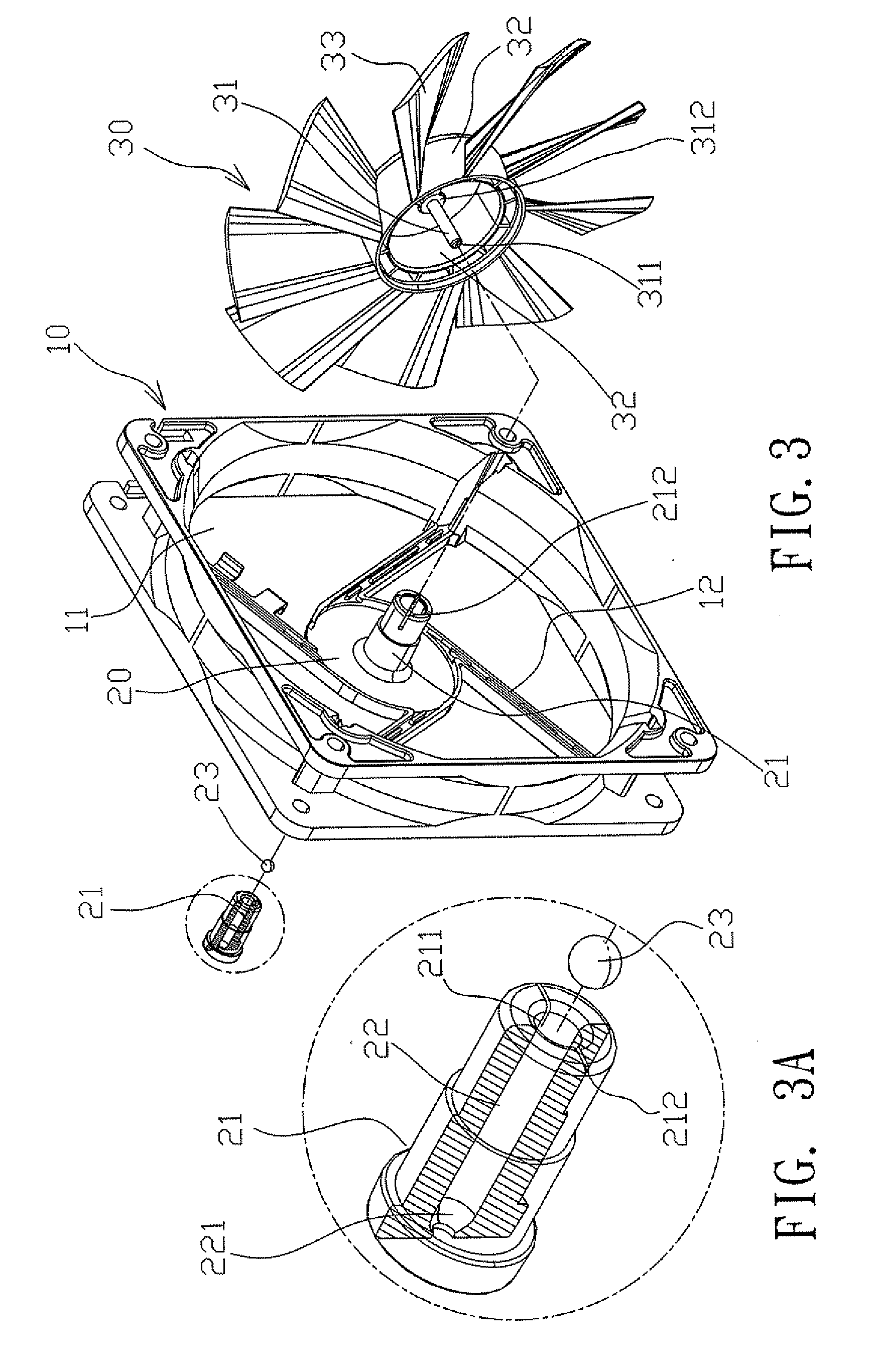
[0023]Referring to FIGS. 3, 3A, 4, 4A and 5 for a preferred embodiment of the present invention, an electric motor apparatus comprises a frame 10, an opening 11 penetrating the frame 10, and a stator 20 and a rotor 30 contained in the frame 10; wherein the stator 20 is installed at the middle of the opening 11, and the periphery of the stator 20 is connected to the frame 10 by a rib 12, and an axle sleeve 21 (which is made of a plastic material in this embodiment) disposed perpendicularly at the central position of the stator 20, and an embedded groove 211 (as shown in FIG. 4A) extended inward and disposed at an internal side of a distal edge of a free end of the axle sleeve 21, and the embedded groove 211 has a slot 212 disposed along its axial direction, such that the sl...


PUM


Abstract

This invention discloses an electric motor apparatus including a frame, a stator and a rotor in the frame, an axle sleeve at the center of the stator and having an embedded groove extended inwardly and at a free end apart from the connecting position of the frame, a bearing sheathed into the axle sleeve, an axle at the center of the rotor and sheathed into the bearing, a latch at an internal side of the rotor and protruded outward for securing the stator and the rotor, and a ball embedded in the bearing and apart from the free end. By the embedded groove and latch, the stator and rotor are combined, and the axle is pressed against the ball. When the axle is rotated, the ball is driven to roll to reduce the friction, noises and wearing as well as enhancing the life expectancy and efficiency of the electric motor.

Description

BACKGROUND OF THE INVENTION[0001]1. Field of the Invention[0002]The present invention relates to an electric motor apparatus capable of reducing friction, and more particularly to an electric motor apparatus that presses an axle at a ball to roll the ball when the axle is rotated, so as to achieve the effects of reducing the friction produced between the axle and the bottom of a bearing, reducing noises and wearing of the axle, and enhancing the life expectancy and efficiency of an electric motor.[0003]2. Description of the Related Art[0004]Referring to FIG. 1 for a heat dissipating fan of a computer in accordance with a prior art, the heat dissipating fan comprises a stator 100, a rotor 200 and a fan body 300 disposed on the rotor 200, wherein the stator 100 is comprised of a bearing 101 disposed at the middle of the stator 100 and a permanent pole 102 disposed at the periphery of the stator 100, and the rotor 200 is comprised of an axle 201 and a permanent magnet 202 disposed arou...

Claims


Application Information

Patent Timeline
Patent Type & Authority Applications(United States)
IPC IPC(8): H02K5/173F04D25/08
CPCF16C17/08F16C17/10H02K7/086H02K5/1675H02K5/1677F16C33/20
Inventor LIN, CHUN-JU
Owner TEK CHAIN TECH
Why Eureka
Try Eureka