Dielectric barrier discharge lamp

a discharge lamp and dielectric barrier technology, applied in the direction of gas discharge lamp details, electric discharge tubes, electrical equipment, etc., can solve the problems of prone to deterioration, electrode configuration does not provide a sufficiently homogenous light, and the planar lamp configuration cannot be used in the majority of existing lamp sockets and lamp housings, etc., to achieve uniform and homogenous discharge, equal size and shape, and good efficiency

Inactive Publication Date: 2009-03-12
GENERAL ELECTRIC CO
View PDF19 Cites 1 Cited by
  • Summary
  • Abstract
  • Description
  • Claims
  • Application Information

AI Technical Summary

Benefits of technology

[0013]The disclosed DBD lamps ensure that the available lamp volume is divided into multiple smaller discharge volumes. These smaller discharge volumes have a substantially equivalent size and shape, and their electrode arrangements are also quite similar. Therefore, all discharge volumes will show very similar radiation characteristics. The arrangement of multiple tubes allow the intermittent placement of electrodes, so that the lines of force of the electric field will extend into the discharge volumes, and the lamp will operate with a good efficiency. If necessary, the electrodes may be located external to the discharge vessel, and yet practically do not cover the external surface of the lamp. Further, no sealed lead-through or any dielectric covering layer film for the electrodes is required. The lamp can provide a uniform and homogenous volume discharge, and a large illuminating surface.

Problems solved by technology

This is advantageous because a thin film dielectric layer is complicated to manufacture and it is prone to deterioration.
On the other hand, a planar lamp configuration can not be used in the majority of existing lamp sockets and lamp housings, which were designed for traditional incandescent bulbs.
It has been found that such an electrode configuration does not provide a sufficiently homogenous light, because the discharge within the relatively large discharge volume tend to be uneven.
Certain volume portions are practically completely devoid of an effective discharge, particularly those volume portions which are further away from both electrodes.
However, the annular shape of the discharge vessel causes certain manufacturing problems, and the external electrodes are visually unattractive, and remain visible even if the discharge vessel is covered by a further external translucent envelope.
However, it has not been suggested to arrange the gas tubes to form a light source body that is substantially cylindrical, and resembles usual incandescent or fluorescent light sources.

Method used


Image

  • Dielectric barrier discharge lamp
  • Dielectric barrier discharge lamp
  • Dielectric barrier discharge lamp

Examples


Embodiment Construction

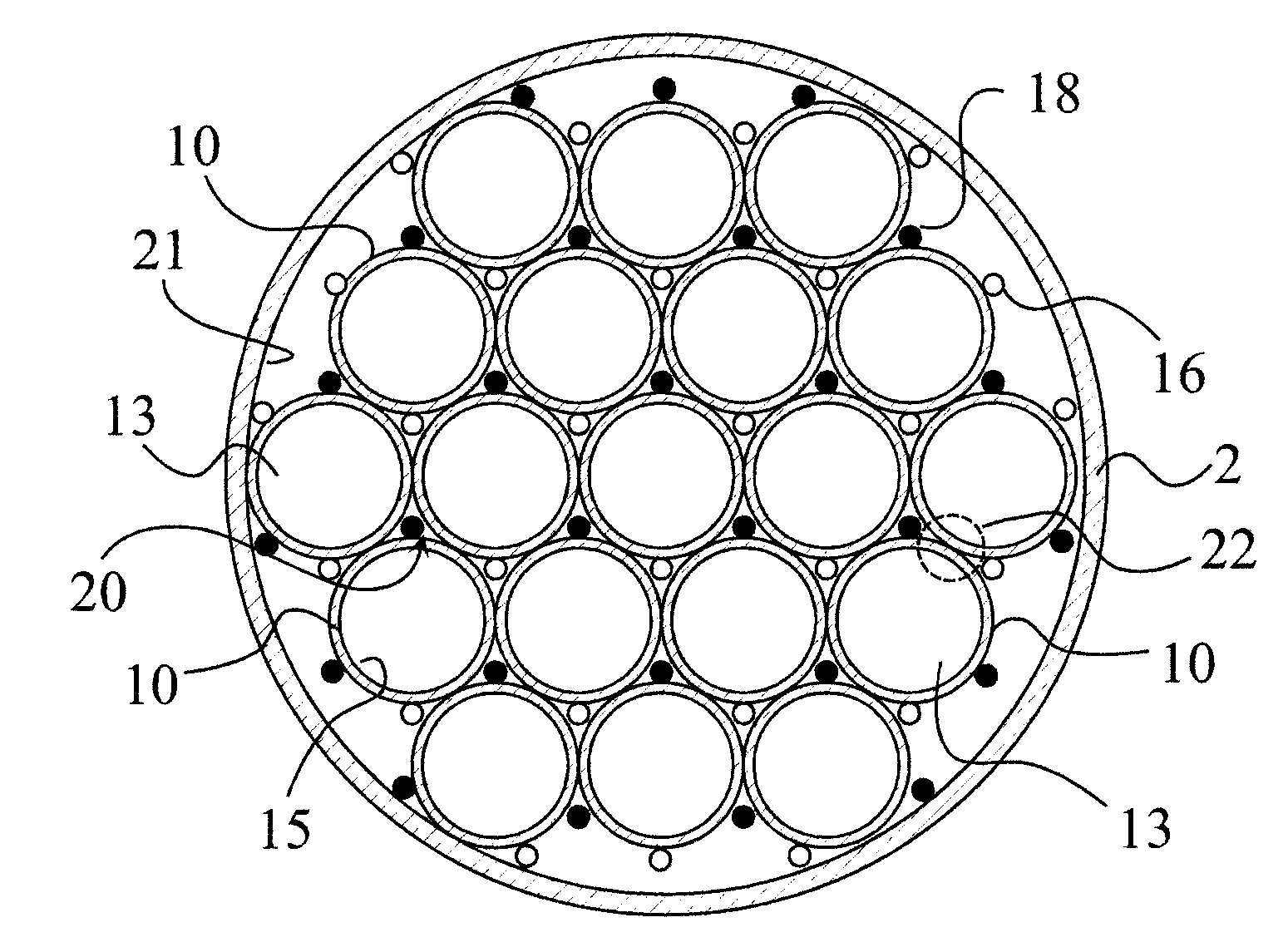
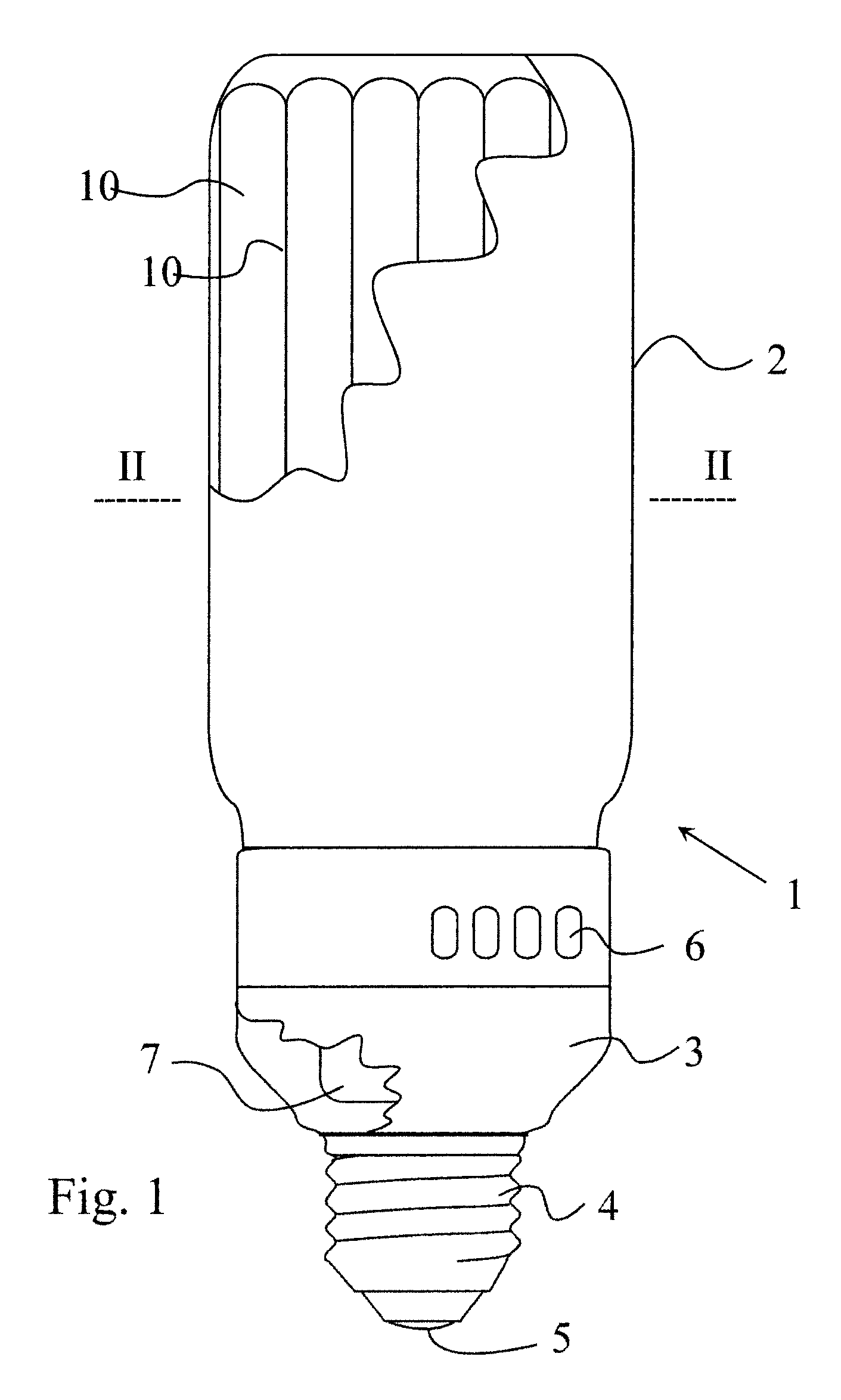
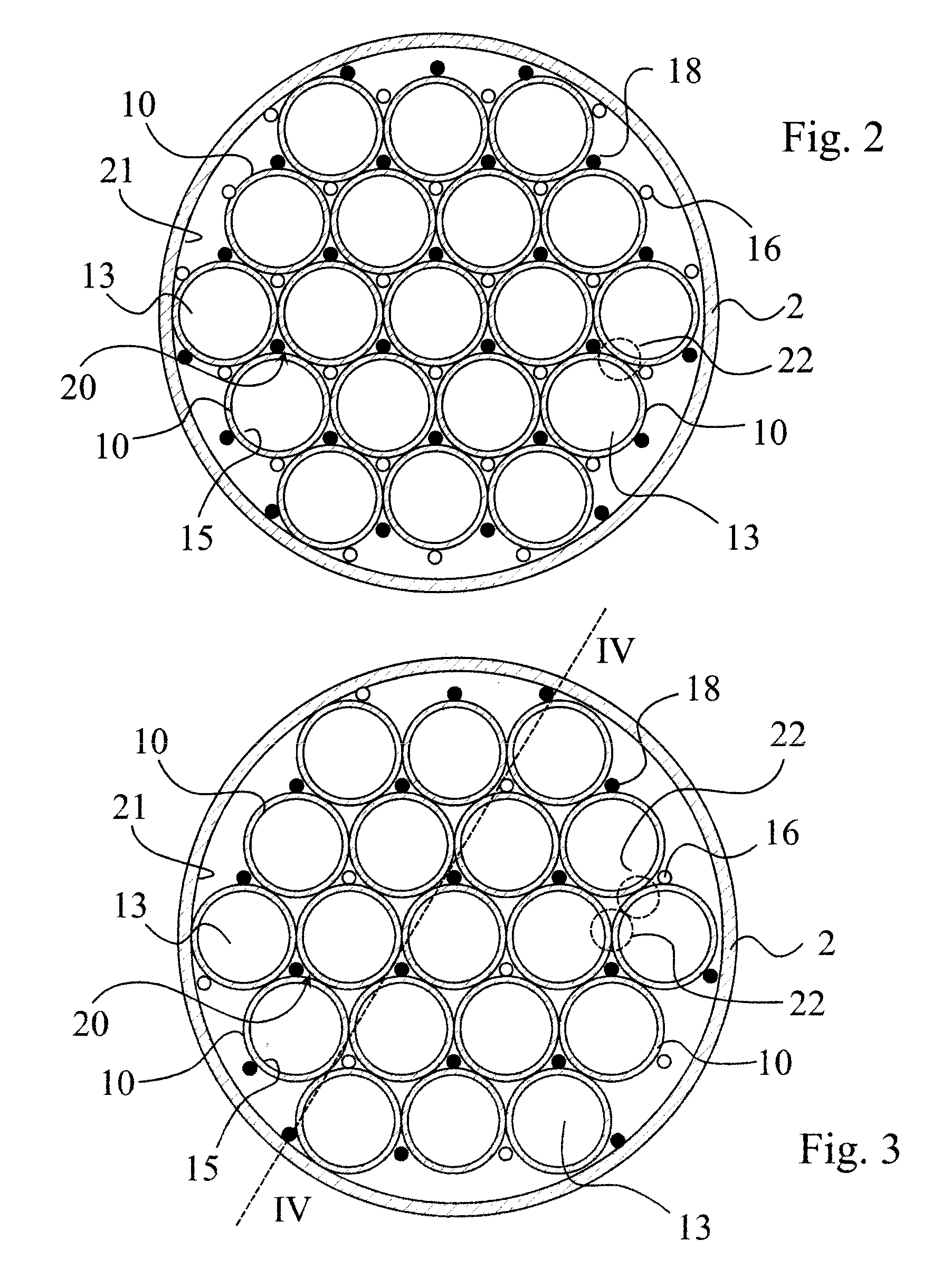
[0021]Referring now to FIG. 1, there is shown a low pressure discharge lamp 1. The lamp is a dielectric barrier discharge lamp (hereinafter also referred to as DBD lamp), with an external envelope 2 enclosing a plurality of discharge vessels 10. In the shown embodiment the external envelope 2 is substantially cylindrical, as well as the discharge vessels 10. The discharge vessels 10 and the external envelope 2 are mechanically supported by a lamp base 3, which also holds the contact terminals 4,5 of the lamp 1, corresponding to a standard screw-in socket. The lamp base also houses an AC power source 7, illustrated only schematically. The AC power source 7 is of a known type, which delivers an AC voltage of 1-5 kV with 50-200 kHz AC frequency, and need not be explained in more detail. The operation principles of power sources for DBD lamps are disclosed, for example, in U.S. Pat. No. 5,604,410. As shown in the embodiment of FIG. 1, ventilation slots 6 may be also provided on the lamp...


PUM


Abstract

A dielectric barrier discharge lamp comprises multiple tubular discharge vessels of a substantially equivalent size and having a principal axis. Each discharge vessel encloses a discharge volume filled with a discharge gas. The discharge vessels are arranged substantially parallel to their principal axis and adjacent to each other. The lamp also comprises a first set of interconnected electrodes and a second set of interconnected electrodes. The electrodes are isolated from the discharge volume by at least one dielectric layer. At least one of the dielectric layers is constituted by the wall of the discharge vessel, and the electrodes of at least one electrode set are located between the discharge vessels. In one embodiment, the discharge vessels are adjacent to each other in a lattice, and the first and second electrode sets are located between the discharge vessels in interstitial voids of the lattice. In another embodiment, the discharge vessels are arranged adjacent to each other along generatrices of a prism.

Description

BACKGROUND OF THE INVENTION[0001]This invention relates to a dielectric barrier discharge lamp.[0002]The majority of the presently known and commercially available low pressure discharge lamps are so-called compact fluorescent lamps. These lamps have a gas fill which also contains small amounts of mercury. Since mercury is a highly poisonous substance, novel types of lamps are being recently developed. One promising candidate to replace mercury-filled fluorescent lamps is the so-called dielectric barrier discharge lamp (shortly DBD lamp). Besides eliminating the mercury, it also offers the advantages of long lifetime and negligible warm-up time.[0003]As explained in detail, for example, in U.S. Pat. No. 6,060,828, the operating principle of DBD lamps is based on a gas discharge in a noble gas (typically Xenon). The discharge is maintained through a pair of electrodes, between which there is at least one dielectric layer. An AC voltage of a few kV with a frequency in the kHz range is...

Claims


Application Information

Patent Timeline
Patent Type & Authority Applications(United States)
IPC IPC(8): H01J65/04
CPCH01J61/327H01J65/046H01J61/92
Inventor REICH, LAJOSMAROS, ISTVANBANKUTI, LASZLOTOKES, JOZSEFNAGY, ZOLTAN
Owner GENERAL ELECTRIC CO
Why Eureka
Try Eureka