
Optical information recording method, optical information recording apparatus, and optical information recording medium

a technology of optical information and recording apparatus, applied in the field of optical information recording method and optical information recording apparatus with respect, can solve the problems of excessive cooling speed after melting with laser irradiation in a portion, inability to record data stably with satisfactory signal quality, constant rising and falling time in modulation and light-emission operations of lasers, etc., to achieve satisfactory signal quality, eliminate insufficient overwrite, and simplify the configuration of the apparatus

Inactive Publication Date: 2009-03-12
PANASONIC CORP
View PDF14 Cites 0 Cited by
  • Summary
  • Abstract
  • Description
  • Claims
  • Application Information

AI Technical Summary

Benefits of technology

"The present invention provides an optical information recording method, apparatus, and optical information recording medium that can stably record and reproduce data with satisfactory signal quality over a wide linear velocity range. The method includes forming a recording pulse with a length that corresponds to the data to be recorded, a recording pulse train with different pulse heights, and a leading pulse for the data. The method can be implemented with a simplified apparatus configuration. The invention also provides a method for controlling the trailing pulse width to improve the quality of the recorded data. Overall, the invention allows for stable recording and reproduction of data with high quality over a wide range of linear velocities."

Problems solved by technology

However, according to the above-mentioned conventional recording / reproducing method, in the case where the range of a linear velocity to be varied is large, data cannot be recorded stably with satisfactory signal quality.
However, there are a constant rising time and falling time in modulation and light-emission operations of laser.
In this case, when the duty ratio of the trailing pulse is low, in recording at a high linear velocity, the cooling speed after melting with laser irradiation increases excessively in a portion where a trailing portion of a mark is formed (i.e., the power level of a laser is shifted from the recording power to the erasure power).
Consequently an amorphous region of a mark back portion is formed too stably, so that insufficient erasure occurs when the mark is overwritten, resulting in a decrease in the quality of reproduced signal.
Consequently, recrystallization proceeds from the periphery of the melted portion, so that the width of a mark front portion becomes small, resulting in a distortion of the mark shape that degrades the quality of a reproduced signal.

Method used


Image

  • Optical information recording method, optical information recording apparatus, and optical information recording medium
  • Optical information recording method, optical information recording apparatus, and optical information recording medium
  • Optical information recording method, optical information recording apparatus, and optical information recording medium

Examples


embodiment 1

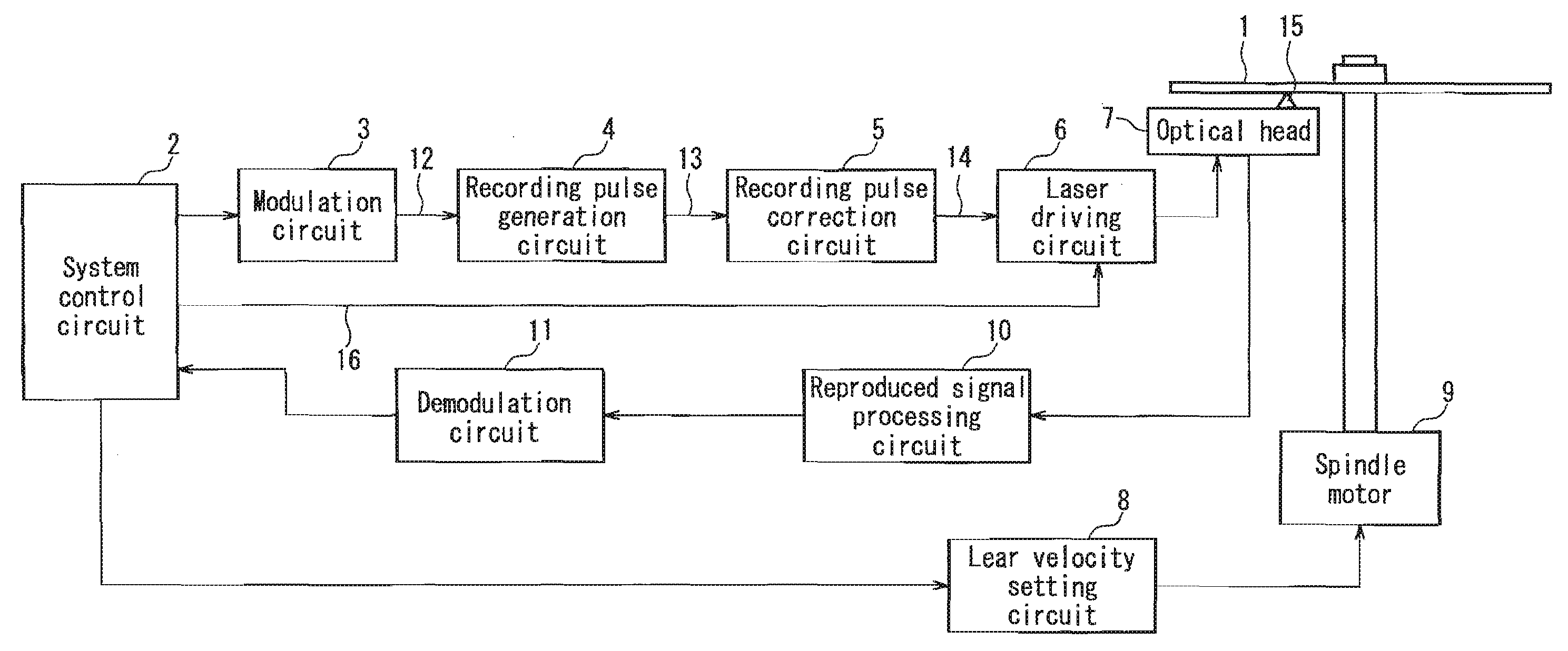
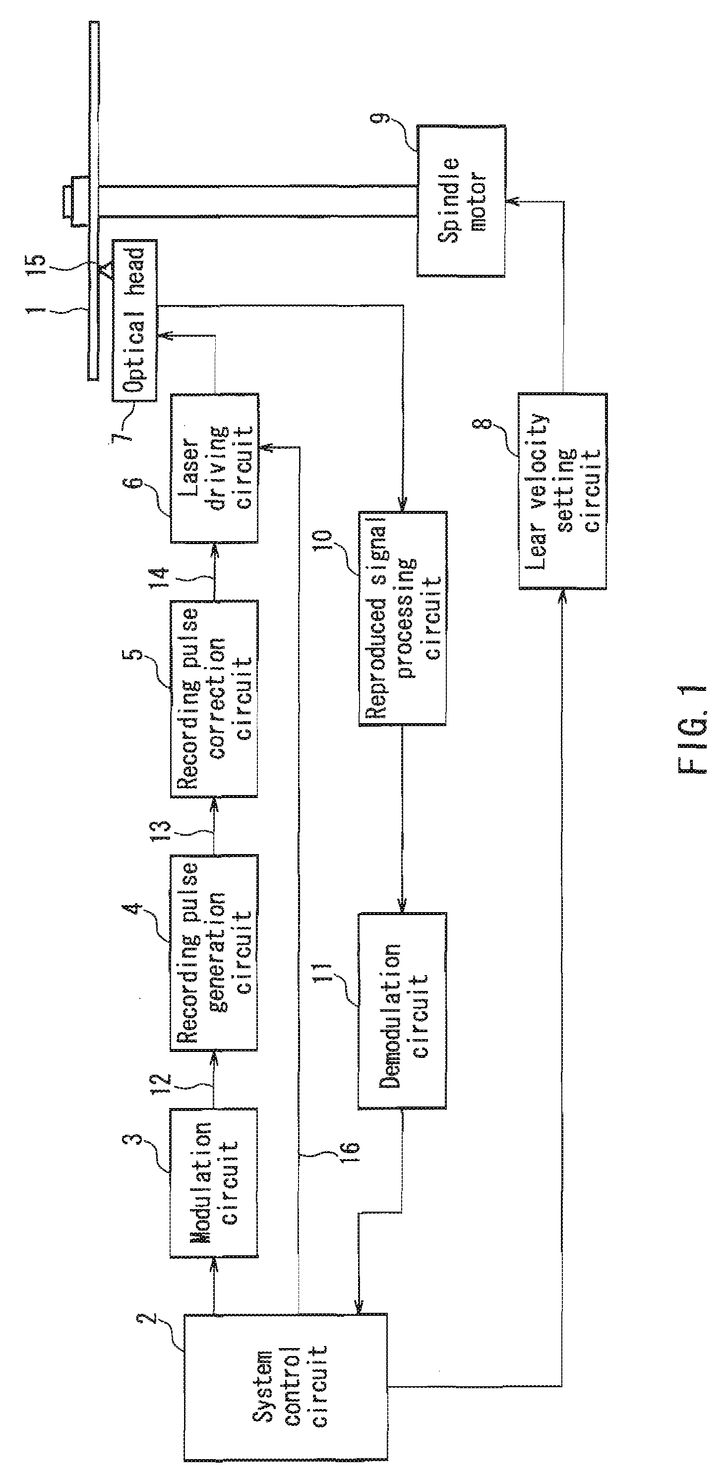
[0098]First, the schematic configuration of an optical information recording apparatus in Embodiment 1 will be described with reference to a block diagram of FIG. 1. Although FIG. 1 shows the optical information recording / reproducing apparatus, the embodiment of the present invention is characterized by the configuration of a portion corresponding to a recording apparatus in this optical information recording / reproducing apparatus. Furthermore, the basic configuration of the optical information recording apparatus shown in FIG. 1 is common to the following respective embodiments.

[0099]Reference numeral 1 denotes an optical disk for recording / reproducing data, and reference numeral 2 denotes a system control circuit for controlling the entire recording / reproducing apparatus. Based on a signal supplied from a system control circuit 2, a modulation circuit 3 generates a binarized modulation signal 12 in accordance with data to be recorded. A recording pulse generation circuit 4 generat...

embodiment 2

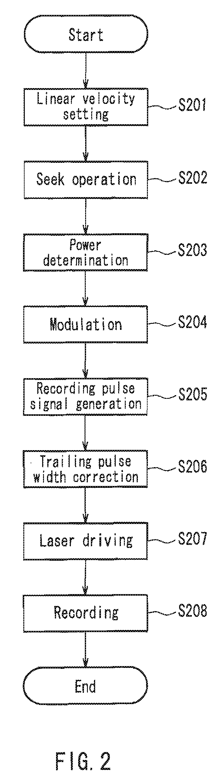
[0128]Next, an optical information recording method and an optical information recording apparatus in Embodiment 2 will be described with reference to the flow chart of FIG. 7 and the operation diagrams of FIGS. 8 to 11. The basic configuration of the optical information recording apparatus in the present embodiment is the same as that of Embodiment 1 shown in FIG. 1.

[0129]FIG. 7 shows a recording procedure according to the optical information recording method of the present embodiment. FIG. 8 shows a signal waveform and a recorded pattern on a track in the case of recording with a high linear velocity by the optical information recording method of the present embodiment. FIG. 9 shows a signal waveform and a recorded pattern in the case of recording with a low linear velocity. FIGS. 10 and 11 respectively show a signal waveform and a recorded pattern when the width of a leading pulse is varied in the case of recording with a low linear velocity. FIGS. 8 to 11 show an operation exemp...

embodiment 3

[0148]In the above-mentioned two embodiments, the case where data is recorded at two kinds of linear velocities: a low linear velocity v1 and a high linear velocity v2 has been described. In a CAV recording system, the linear velocity and the transfer rate are varied continuously depending upon the recording / reproducing position on a medium. In such a case, it is preferable that, by smoothly connecting the light-emission waveform at the low linear velocity v1 to the light-emission waveform at the high linear velocity v2, the light-emission waveform at an intermediate linear velocity is determined. The present embodiment is an example in which the optical information recording method of Embodiment 1 or 2 is configured in such an embodiment.

[0149]FIG. 12 shows an example of setting a trailing pulse width when data is recorded with a linear velocity varied continuously in a range of v1 to v2 in Embodiment 1. At the linear velocity v1, light is emitted with the light-emission waveform o...


PUM

PropertyMeasurementUnit
lengthaaaaaaaaaa
heightsaaaaaaaaaa
linear velocitiesaaaaaaaaaa

Abstract

A recording pulse for driving a laser is formed so that a length of a recorded mark on a recording medium corresponds to a recording code length of data; the recording pulse is formed as a recording pulse train having pulse heights corresponding to a plurality of power levels including a recording power and an erasure power; the recording pulse train is composed of a plurality of pulses including a multi-pulse and a trailing pulse; and the recording medium at a plurality kinds of linear velocities is irradiated with laser light based on the recording pulse to form the mark. When linear velocities v1 and v2 are in a relationship that v1<v2, the following formulas are satisfied: (TL1 / Tw1)<(TL2 / Tw2), and ((TM2 / Tw2) / (TM1 / Tw1))<((TL2 / Tw2) / (TL1 / Tw1)), where Tw1, Tw2: channel dock periods at the linear velocities v1, v2, TL1, TL2: trailing pulse widths at the linear velocities v1, v2, TM1, TM2: multi-pulse widths at the linear velocities v1, v2.

Description

[0001]This application is a division of U.S. Ser. No. 11 / 080,142, filed Mar. 15, 2005 which application is incorporated herein by reference.BACKGROUND OF THE INVENTION[0002]1. Field of the Invention[0003]The present invention relates to an optical information recording method and an optical information recording apparatus with respect to a recording medium used for optically recording / reproducing data. In particular, the present invention relates to the improvement of a recording pulse waveform with respect to a medium used for recording data at a plurality of different linear velocities.[0004]2. Description of the Related Art[0005]Recently, as a medium for optically recording data, an optical disk, an optical card, an optical tape, and the like have been proposed and developed. Among them, an optical disk is receiving attention as a medium capable of recording / reproducing data with a large capacity and a high density.[0006]For example, in the case of a phase-change type optical dis...

Claims


Application Information

Patent Timeline
Patent Type & Authority Applications(United States)
IPC IPC(8): G11B7/0045G11B7/006
CPCG11B7/0062G11B7/004G11B7/0045
Inventor NARUMI, KENJIHOSAKA, TOMIHARU
Owner PANASONIC CORP
Features
  • Generate Ideas
  • Intellectual Property
  • Life Sciences
  • Materials
  • Tech Scout
  • Unparalleled Data Quality
  • Higher Quality Content
  • 60% Fewer Hallucinations
Learn More