
Diffraction pattern detection in a transmission charged particle microscope

a technology of transmission charge and particle microscope, which is applied in the direction of basic electric elements, electric discharge tubes, electrical apparatus, etc., can solve the problems of radiation damage to specimens, especially biological samples, and degradation of signal quality, so as to reduce the risk of detector damage, the average dose rate per pixel is reduced, and the count rate is higher

Active Publication Date: 2021-05-11
FEI CO
View PDF1 Cites 0 Cited by
  • Summary
  • Abstract
  • Description
  • Claims
  • Application Information

AI Technical Summary

Benefits of technology

The present patent aims to provide a solution for recording diffraction patterns from low-dose situations with satisfactory signal quality. The invention proposes a method using a detector with a high Detective Quantum Efficiency (DQE) and a relatively high beam / detector relative motion during each frame recording. This results in a higher count rate and a reduction of pile-ups. The diffraction pattern is moved along a known locus, and the original pattern can be accurately determined by applying a straightforward deconvolution to each frame. The techniques described herein can be used in low-dose inorganic and organic samples to reveal higher-resolution structures and mitigate the risk of detector damage. The detector used can be a CCD or CMOS sensor, with the advantage of adaptive readout rates for improved dynamic range.

Problems solved by technology

Charged-particle irradiation generally causes radiation damage to specimens, especially biological samples.
Such low-dose operation, however, tends to cause a degradation in signal quality.

Method used


Image

  • Diffraction pattern detection in a transmission charged particle microscope
  • Diffraction pattern detection in a transmission charged particle microscope

Examples


Embodiment Construction

diment 1

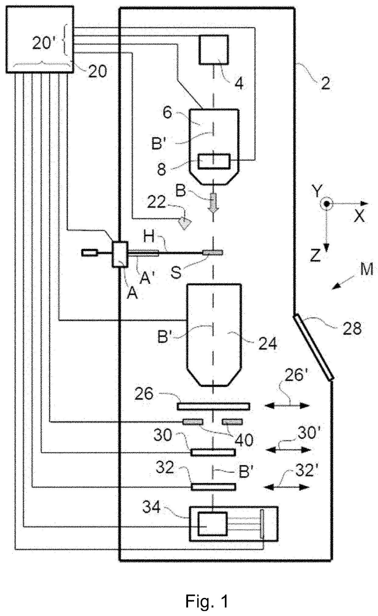
[0030]FIG. 1 (not to scale) is a highly schematic depiction of an embodiment of a TCPM M in which the present invention is implemented; more specifically, it shows an embodiment of a TEM / STEM (though, in the context of the current disclosure, it could just as validly be an ion-based microscope, for example). In the Figure, within a vacuum enclosure 2, an electron source 4 produces a beam B of electrons that propagates along an electron-optical axis B′ and traverses an electron-optical illuminator (charged particle beam column) 6, serving to direct / focus the electrons onto a chosen part of a specimen S (which may, for example, be (locally) thinned / planarized). Also depicted is a deflector 8, which (inter alia) can be used to effect scanning motion of the beam B.

[0031]The specimen S is held on a specimen holder H that can be positioned in multiple degrees of freedom by a positioning device / stage A, which moves a cradle A′ into which holder H is (removably) affixed; for example...


PUM


Abstract

Techniques of using a Transmission Charged Particle Microscope for diffraction pattern detection are disclosed. An example method including irradiating at least a portion of a specimen with a charged particle beam, using an imaging system to collect charged particles that traverse the specimen during said irradiation, and to direct them onto a detector configured to operate in a particle counting mode, using said detector to record a diffraction pattern of said irradiated portion of the specimen, recording said diffraction pattern iteratively in a series of successive detection frames, and during recording of each frame, using a scanning assembly for causing relative motion of said diffraction pattern and said detector, so as to cause each local intensity maximum in said pattern to trace out a locus on said detector.

Description

BACKGROUND OF THE INVENTION[0001]Charged-particle microscopy is a well-known and increasingly important technique for imaging microscopic objects, particularly in the form of electron microscopy. Historically, the basic genus of electron microscope has undergone evolution into a number of well-known apparatus species, such as the Transmission Electron Microscope (TEM), Scanning Electron Microscope (SEM), and Scanning Transmission Electron Microscope (STEM), and also into various sub-species, such as so-called “dual-beam” apparatus (e.g. a FIB-SEM), which additionally employ a “machiningFocused Ion Beam (FIB), allowing supportive activities such as ion-beam milling or Ion-Beam-Induced Deposition (MID), for example. More specifically:[0002]In an SEM, irradiation of a specimen by a scanning electron beam precipitates emanation of “auxiliary” radiation from the specimen, in the form of secondary electrons, backscattered electrons, X-rays and cathodoluminescence (infrared, visible and / ...

Claims


Application Information

Patent Timeline
Patent Type & Authority Patents(United States)
IPC IPC(8): H01J37/26H01J37/22H01J37/147H01J37/244
CPCH01J37/222H01J37/147H01J37/244H01J37/26H01J2237/226H01J2237/2446H01J2237/24455H01J2237/24495H01J2237/2605H01J2237/2617H01J2237/2802H01J2237/2803H01J2237/2809H01J37/28
Inventor BUIJSSE, BARTKUIJPER, MAARTEN
Owner FEI CO
Features
  • Generate Ideas
  • Intellectual Property
  • Life Sciences
  • Materials
  • Tech Scout
  • Unparalleled Data Quality
  • Higher Quality Content
  • 60% Fewer Hallucinations
Learn More