Developing device, process cartridge, and image forming apparatus

a development device and process cartridge technology, applied in electrographic process devices, instruments, optics, etc., can solve problems such as image degradation, inability to develop properly, and increased possibility of leakage between electrodes, so as to prevent adhesion of toner

Inactive Publication Date: 2009-03-12
RICOH KK
View PDF19 Cites 22 Cited by
  • Summary
  • Abstract
  • Description
  • Claims
  • Application Information

AI Technical Summary

Benefits of technology

[0016]With the foregoing in view, it is an object of the present invention to provide a developing device constituted so as to be capable of causing the toner to flare properly, and properly carry out developing in the developing area, by preventing adhesion of toner to the toner carrier.

Problems solved by technology

However, if F1 is smaller than F2, the toner stays adhering to the toner carrier surface and cannot flare, so developing does not occur properly.
Also, the voltage is applied by applying a large potential difference between electrodes, so the possibility for the occurrence of leakage between electrodes becomes larger.
In this case, it is possible that the toner in cloud form will adhere to the charge retention surface, and this has the problem that contamination is caused.
Also, there is the possibility that the developed toner image will be disturbed by the toner that was once retained on the charge retention surface, so image degradation will occur.
Therefore, if most of the toner adheres, it will affect the toner that comes subsequently, which is a problem.

Method used


Image

  • Developing device, process cartridge, and image forming apparatus
  • Developing device, process cartridge, and image forming apparatus
  • Developing device, process cartridge, and image forming apparatus

Examples


embodiment 1

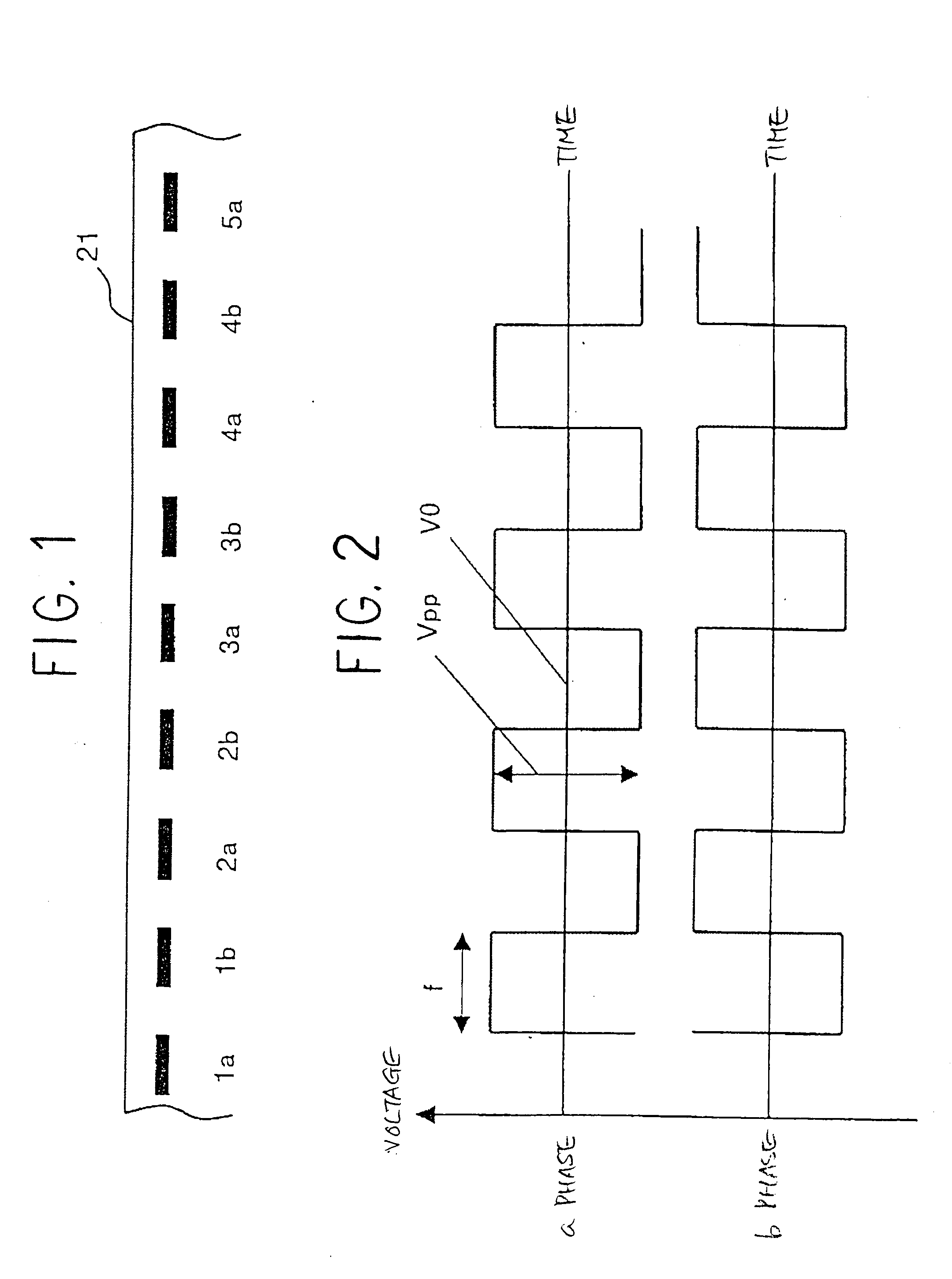
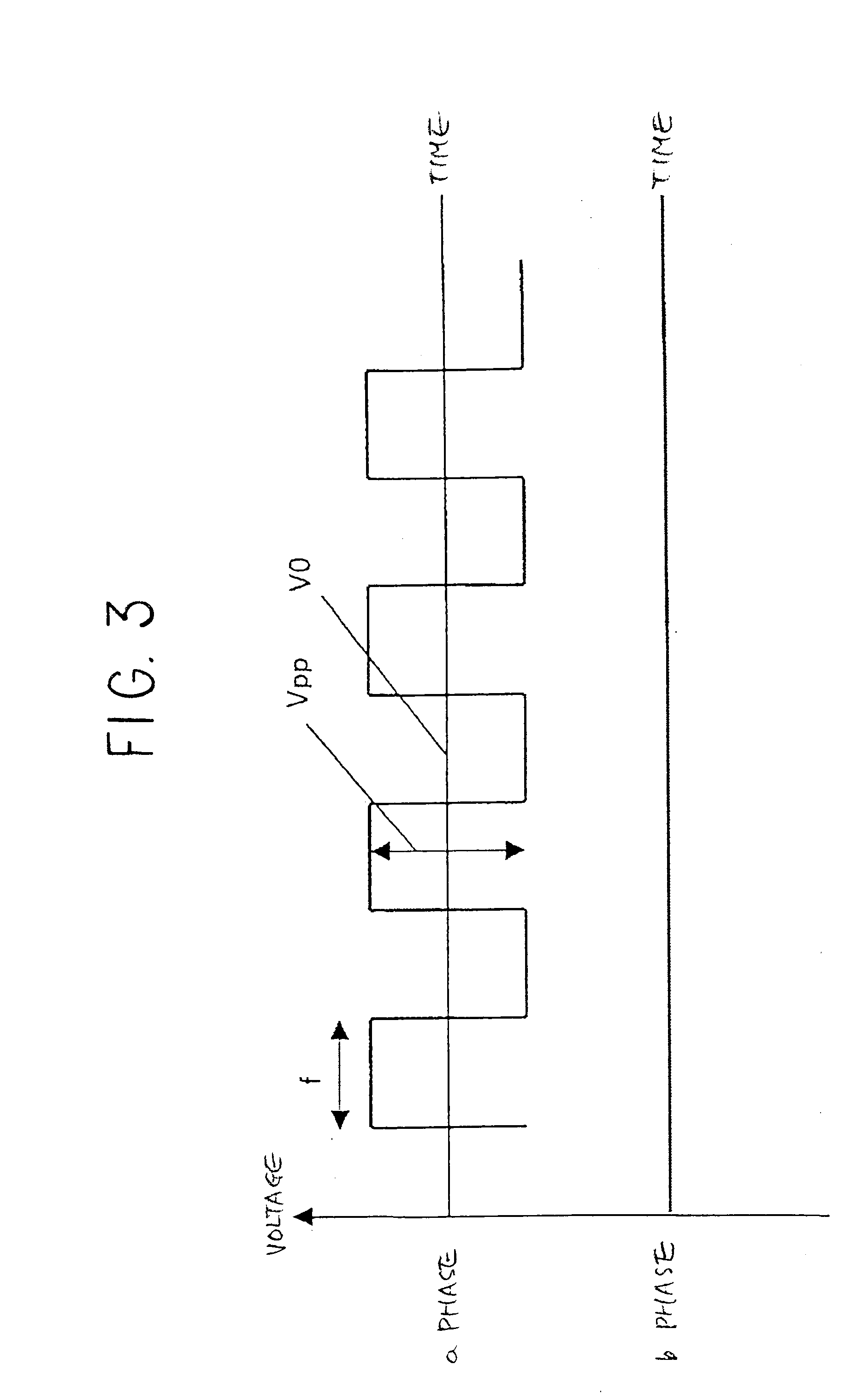
[0044]FIG. 1 shows an example of the constitution of the electrodes of the toner carrier used in a developing device according to the present embodiment. In the constitution in FIG. 1, the width of electrodes of a toner carrier 21 is 40 μm, and the distance between electrodes is 40 μm. Also, the electrodes of the toner carrier 21 are two phase, the odd numbered electrodes 1a, 2a, 3a, 4a, 5a, . . . are the a phase, and the even numbered electrodes 1b, 2b, 3b, 4b, 5b, . . . are the b phase. FIGS. 2 and 3 show examples of the voltage applied to the a phase and b phase of the electrodes of the toner carrier 21.

[0045]In FIG. 2, the voltage is a rectangular wave, with the voltages of the a phase and b phase applied with their phases shifted by π. As a result of this phase difference there is always a potential difference of Vpp between the a phase and the b phase. An electric field is generated between the electrodes by this potential difference, and the toner is made to hop between the e...

embodiment 2

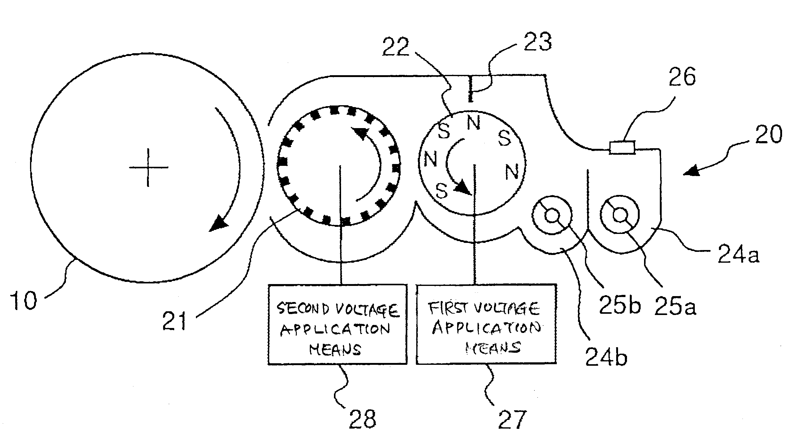
[0054]Next, FIG. 6 is a diagram showing the schematic constitution of a developing device according to the present embodiment. An example of a developing device 30 is shown that uses one-component developing agent made from non-magnetic toner. The toner is housed in a developing agent housing unit 34, and is agitated by toner replenishment rollers 35a, 35b. Through the action of the toner replenishment roller 35b, the toner is becomes electrostatically charged by friction with a toner supply member 32. The toner is scooped up onto the toner supply member 32 by the electrostatic force. The toner on the toner supply member 32 is reduced to a thin layer by a developing agent layer control member 33. The toner is transported by the rotation of the toner supply member to a position in opposition to a toner carrier 31 having the electrode constitution as described previously.

[0055]A supply bias is applied to the toner supply member 32 by first voltage application means 37. The supply bias...

embodiment 3

[0057]FIG. 7 is a diagram showing the schematic constitution of a developing device according to the present embodiment. An example of a developing device 40 having toner recovery means disposed on the downstream side of the developing area relative to the direction of transport of the toner is shown. In FIG. 7, reference numeral 41 is a toner carrier, 42 is a toner supply member (or a developing agent carrier), and 43 is a developing agent layer control member. These members are the same as the constituent members of developing device shown in FIG. 5 or FIG. 6, and their operation is also the same. Also, reference numerals 45a, 45b are agitation and transport members.

[0058]Various methods may be considered for the toner recovery means. FIG. 7 shows toner recovery using a recovery plate 46 and a vibrator 47. A direct current voltage is applied between the toner carrier 41 and the recovery plate 46 by voltage application means 48, that generates an electric field so that a force acts...


PUM


Abstract

A developing device constituted to be capable of reliably making toner flare, and carrying out developing normally in the developing area, by preventing toner from adhering to the toner carrier. A developing device having a toner carrier which is disposed in opposition to a latent image carrier and which carries toner for developing an electrostatic latent image on the latent image carrier, the developing device including: a plurality of electrodes aligned at a predetermined interval within the toner carrier; voltage application means for applying a voltage to the electrodes so that the electric field between the plurality of electrodes varies with time, wherein the electric field between the electrodes causes the toner on the toner carrier to hop and form a cloud; and a toner adhesion prevention member that is provided upstream of a developing area where the latent image carrier is in opposition to the toner carrier and that prevents adhesion of toner to the toner carrier. According to the developing device, it is possible to prevent toner from adhering to the toner carrier, and it is possible to make the toner flare reliably.

Description

BACKGROUND OF THE INVENTION[0001]1. Field of the Invention[0002]The present invention relates to a developing device that develops electrostatic latent images on a latent image carrier using toner, a process cartridge provide with the developing device, and an image forming apparatus such as a copier, printer, plotter, facsimile machine, or a multi-function machine that combines these functions, that is provided with the developing device or the process cartridge.[0003]2. Description of the Related Art[0004]As the conventional technology of developing devices that develop electrostatic latent images on an image carrier using toner, Japanese Patent Application Laid-open No. 2005-010348 (Prior Art 1), for example, discloses a developing device that develops electrostatic latent images in a non-contact manner by transferring toner from a donor structure to a charge carrying surface. The developing device includes an electrode provided between the donor structure and the charge carrying...

Claims


Application Information

Patent Timeline
Patent Type & Authority Applications(United States)
IPC IPC(8): G03G15/08
CPCG03G15/0806G03G2215/0651G03G2215/0643
Inventor NAKAGAWA, YOSHINORIISHII, YASUYUKIKOSUGI, HIDEKITAKAHASHI, TOMOKOYAMADA, MASAAKIKADOTA, ICHIRO
Owner RICOH KK
Why Eureka
Try Eureka