Variable area turbine vane arrangement

a turbine and variable area technology, applied in the direction of machines/engines, reaction engines, liquid fuel engines, etc., can solve the problems of reducing the structural integrity and durability of the nozzle segments, reducing the pressure loss of the turbine, and leaking, etc., to reduce the cost and weight, the effect of reducing the loss of the turbine pressur

Inactive Publication Date: 2009-03-12
UNITED TECH CORP
View PDF22 Cites 21 Cited by
  • Summary
  • Abstract
  • Description
  • Claims
  • Application Information

AI Technical Summary

Benefits of technology

[0007]The present invention therefore provides a variable area turbine nozzle having relatively uncomplicated rotation, support and

Problems solved by technology

Although it would be desirable to obtain variable flow through turbine nozzles by adjusting the throat areas thereof, previous attempts thereat have proved difficult because of severe operating environment of the turbine nozzles.
Nozzle vanes are also sub

Method used


Image

  • Variable area turbine vane arrangement
  • Variable area turbine vane arrangement
  • Variable area turbine vane arrangement

Examples


Embodiment Construction

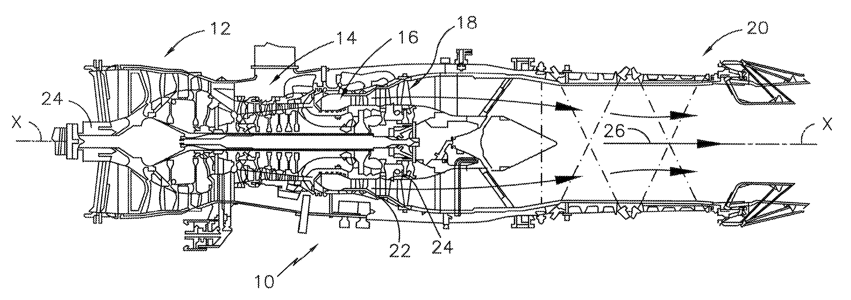
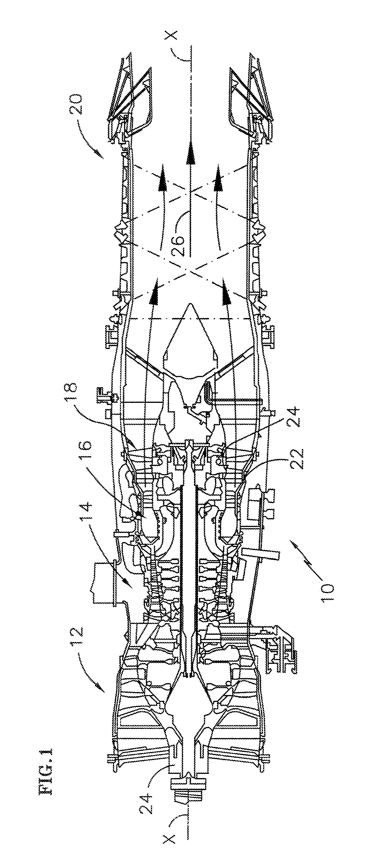
[0013]FIG. 1 schematically illustrates a gas turbine engine 10 which generally includes a fan section 12, a compressor section 14, a combustor section 16, a turbine section 18, and a nozzle section 20 along a longitudinal axis X. The gas turbine engine 10 of the disclosed embodiment is a relatively low bypass gas turbine engine. Although the disclosed embodiment illustrates a 3-stage fan, a 6-stage compressor, an annular combustor, a single stage high-pressure turbine, and a 2-stage low pressure turbine, various other gas turbine engines will benefit from the present invention.

[0014]The engine 10 is configured to provide a variable area turbine nozzle to selectively control the flow of the combustion gas 12 from the combustor section 16 through the turbine section 18. The engine 10 is also referred to as including a Controlled Area Turbine Nozzle (CATN).

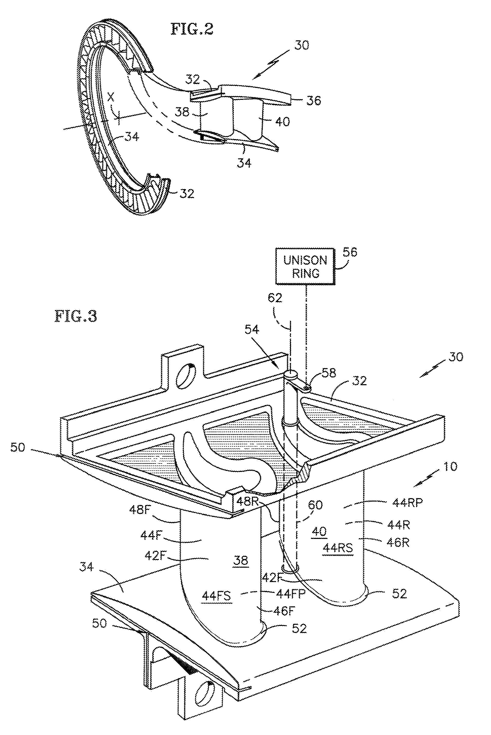
[0015]Referring to FIG. 2, a turbine nozzle segment 30 includes an arcuate outer vane platform segment 32 and an arcuate inner vane...


PUM


Abstract

A turbine section of a gas turbine engine includes a ring of turbine nozzle segments each having paired turbine vanes. Turbine throat area is modulated by rotating each rotational turbine vanes about an axis of rotation which is located such that rotation changes the turbine throat area concurrently between one rotational stator vane and two adjacent fixed turbine vanes. Each paired turbine vane doublet includes at least one rotational turbine vane between two fixed turbine vanes.

Description

BACKGROUND OF THE INVENTION[0001]The present invention relates to a gas turbine engine turbine section, and more particularly to a ring of paired turbine vanes doublets in which one vane of each doublet rotates to modulate turbine throat area.[0002]The core engine of a gas turbine engine typically includes a multistage axial compressor which provides compressed air to a combustor wherein it is mixed with fuel and ignited for generating hot combustion gas which flows downstream through a high pressure turbine nozzle and in turn through one or more stages of turbine rotor blades. The high pressure turbine blades are joined to a rotor disk which is joined to the compressor by a corresponding drive shaft, with the turbine blades extracting energy for powering the compressor during operation. In a two spool engine, a second shaft joins a fan upstream of the compressor to a low pressure turbine disposed downstream from the high pressure turbine.[0003]Typical turbine nozzles, such as high ...

Claims


Application Information

Patent Timeline
IPC IPC(8): F04D29/56
CPCF01D17/162
Inventor SULJAK, JR., GEORGE T.
Owner UNITED TECH CORP
Why Eureka
Try Eureka