
Semiconductor device and manufacturing method thereof

a technology of semiconductors and semiconductors, applied in the direction of semiconductor devices, basic electric elements, electrical equipment, etc., can solve the problem of inability to obtain desirable electric characteristics, and achieve the effect of desirable electric characteristics

Inactive Publication Date: 2009-03-12
ROHM CO LTD
View PDF4 Cites 7 Cited by
  • Summary
  • Abstract
  • Description
  • Claims
  • Application Information

AI Technical Summary

Benefits of technology

[0006]An object of the present invention is to provide a semiconductor device in which a main current flows in a direction of the thickness of a semiconductor substrate that enables to attain desirable electric characteristics when semiconductor elements with a different function are adjacently arranged.
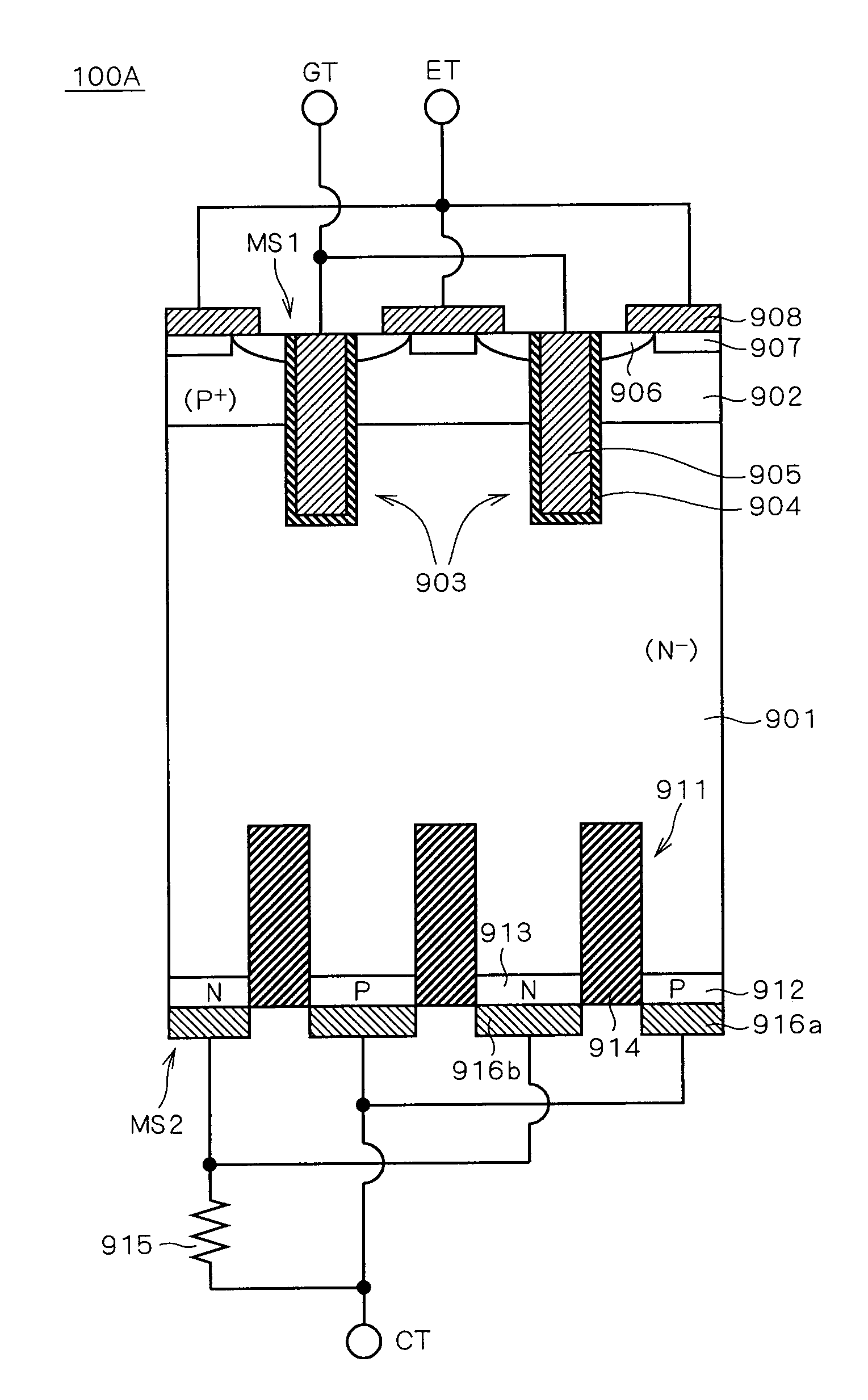
[0008]The semiconductor device of the present invention is applicable, for example, in a case where the first impurity region is used as a drain region of a MOSFET element and a cathode region of a diode element and the second impurity region is used as a collector region of an IGBT element. In this case, the presence of at least one trench isolation structure causes a resistance value of a current path during an IGBT element operation to increase and a current that flows through the current path upon modulation to decrease. Therefore, snapback can be suppressed. Further, by providing at least one trench isolation structure, snapback can be suppressed without reducing the proportion of an area of an effective region (the sum of areas of the first impurity region and the second impurity region) in the second main surface. Therefore, an increase of an ON voltage during an IGBT element operation and a forward voltage Vf during a diode element operation as well as an increase of a local current density during respective operations can be prevented.
[0010]According to the manufacturing method of the semiconductor device of the present invention, at least one trench isolation structure provides, for example, a configuration where an impurity region functioning as a drain region of a MOSFET element and a cathode region of a diode element is separated from an impurity region functioning as a collector region of an IGBT element. Under this configuration, the presence of at least one trench isolation structure causes a resistance value of a current path during a MOSFET element operation to increase and a current that flows through the current path upon modulation to decrease. Therefore, snapback can be suppressed. Further, by providing at least one trench isolation structure, snapback can be suppressed without reducing the proportion of an area of an effective region (the sum of areas of the first impurity region and the second impurity region) in the second main surface. Therefore, an increase of an ON voltage during an IGBT element operation and a forward voltage Vf during a diode element operation as well as an increase of a local current density during respective operations can be prevented.

Problems solved by technology

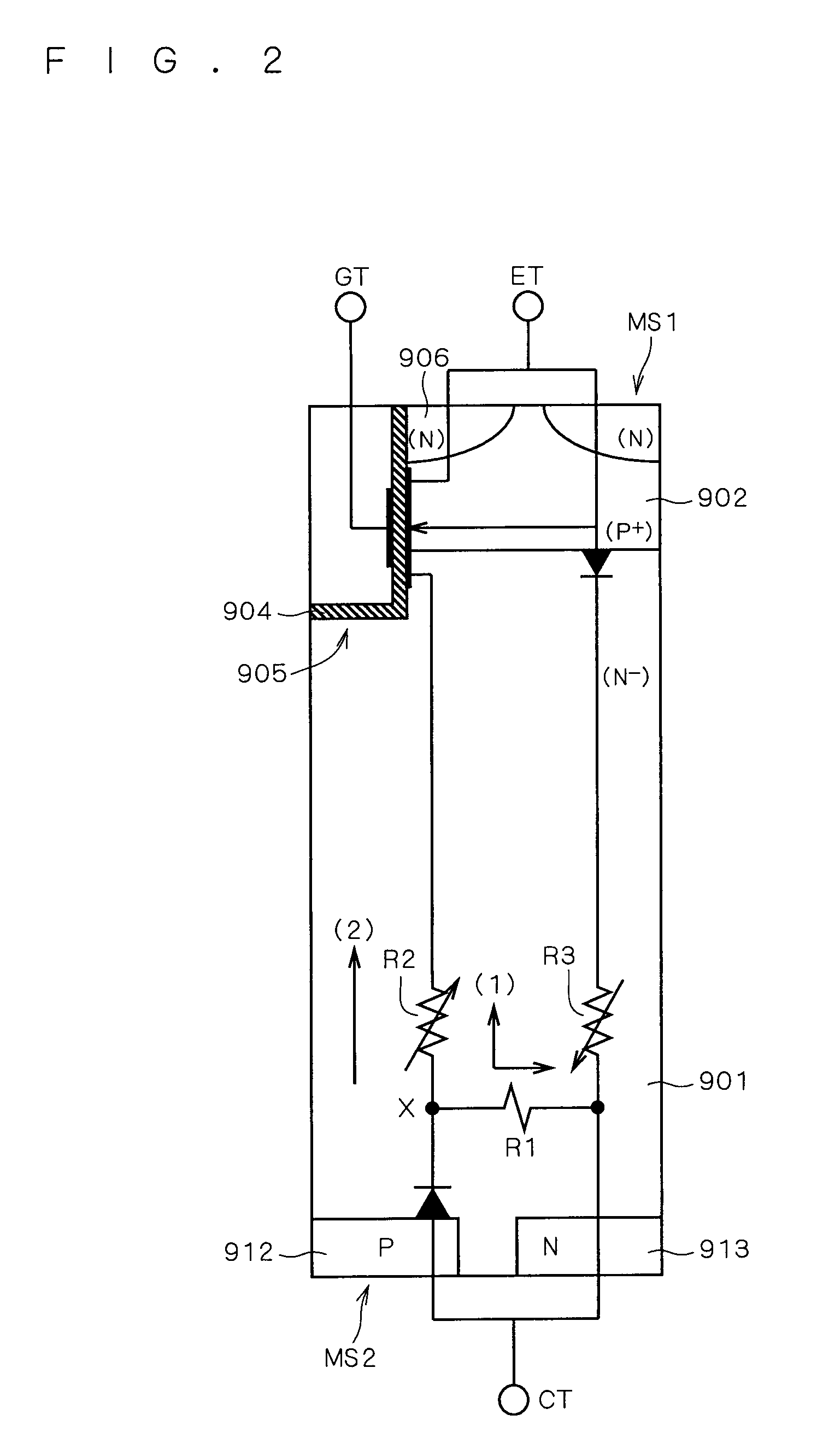
In such a structure, since the P type impurity regions and the N type impurity regions on the second main surface side are in contact with each other, for example, a phenomenon called snapback occurs, resulting in a loss of energy in a switching operation of an IGBT element, thereby leading to an inability to obtain desirable electric characteristics.

Method used


Image

  • Semiconductor device and manufacturing method thereof
  • Semiconductor device and manufacturing method thereof
  • Semiconductor device and manufacturing method thereof

Examples


Embodiment Construction

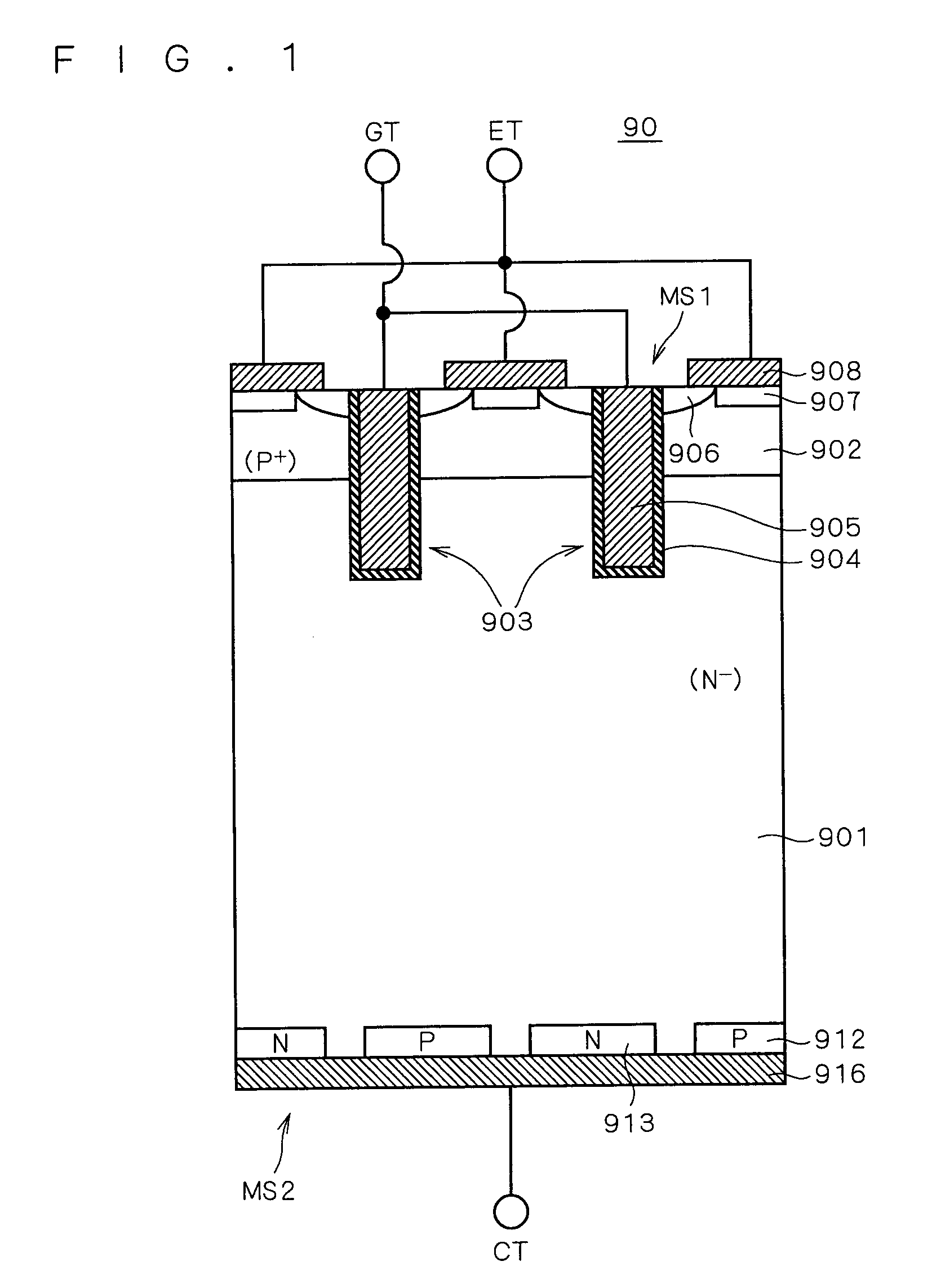
[0031]Prior to describing an embodiment according to the present invention, description is given as to how the technical idea of the present invention has been developed with reference to FIGS. 1 through 3.

[0032]FIG. 1 is a section view illustrating a basic structure of a semiconductor device 90 intended to solve the problem with the conventional semiconductor device.

[0033]In the configuration of the semiconductor device 90 shown in FIG. 1, a P type semiconductor region 902 is formed entirely across in a surface of a first main surface MS1 of a semiconductor substrate 901 that is an N type substrate having a high specific resistance (N−).

[0034]Then, two trenches 903 are provided penetrating the P type semiconductor region 902 from the first main surface MS1 and reaching inside the semiconductor substrate 901. Inner walls of trenches 903 are covered with gate insulating films 904. Further, conductive materials fill inside trenches 903 covered with the gate insulating films 904 to for...


PUM


Abstract

A semiconductor device in which a main current flows in a direction of the thickness of a semiconductor substrate, to attain desirable electric characteristics. P type semiconductor regions and N type semiconductor regions are alternately provided with an interval therebetween, both regions in a surface of a second main surface of a semiconductor substrate. Between the P type semiconductor regions and the N type semiconductor regions, trenches formed in the surface of the semiconductor substrate are filled with insulators, thereby forming trench isolation structures. Moreover, a second main electrode is formed in contact with both the P type semiconductor regions and the N type semiconductor regions.

Description

CROSS-REFERENCE TO RELATED APPLICATIONS[0001]This application is a Divisional of U.S. patent application Ser. No. 10 / 515,346, filed Dec. 3, 2004, which is a 371 of International Patent Application No. PCT / JP2003 / 07168. The entire contents of U.S. patent application Ser. No. 10 / 515,346 are incorporated herein by reference in their entirety.TECHNICAL FIELD[0002]The present invention relates to a semiconductor device, and more specifically, a semiconductor device in which a main current flows in a direction of the thickness of a semiconductor substrate.BACKGROUND ART[0003]As an example of a semiconductor device in which a main current flows in a direction of the thickness of a semiconductor substrate, a structure is suggested where an IGBT (insulated gate bipolar transistor) element and a diode element in parallel connection with the IGBT element are adjacently formed.[0004]For example, Japanese Patent Application Laid-Open No. 11-097715 discloses an example where gate electrode struct...

Claims


Application Information

Patent Timeline
Patent Type & Authority Applications(United States)
IPC IPC(8): H01L21/762H01L29/08H01L29/739
CPCH01L29/0649H01L29/0696H01L29/0834H01L29/7397H01L2924/0002H01L2924/00
Inventor TOKUDA, NORIFUMIKUSUNOKI, SHIGERU
Owner ROHM CO LTD
Learn More