Robot system

a robot system and power feeding technology, applied in the direction of electric programme control, program control, instruments, etc., to achieve the effect of eliminating risks, preventing the activation of operation, and high safety

Active Publication Date: 2009-03-12
YASKAWA DENKI KK
View PDF16 Cites 40 Cited by
  • Summary
  • Abstract
  • Description
  • Claims
  • Application Information

AI Technical Summary

Benefits of technology

[0017]According to the first to fourth aspects of the invention, the feeding unit is provided which not only charges the battery but also issues the signal corresponding to the release of interlock for the robot to perform the operation of the operation program by the teaching unit being correctly disposed in the feeding unit for charging the battery, and the repeat of the operation program is started when the operation start command of the operation program (the activation signal) is inputted while the signal is being issued which corresponds to the release of interlock.
[0018]By this action, the robot system with high safety can be provided which prevents the

Problems solved by technology

However, when the operator registers a position of the robot in the vicinity of the robot, the cable of the teaching unit gets entangled with equipment lying on the periphery of the robot or

Method used


Image

  • Robot system
  • Robot system
  • Robot system

Examples


embodiment 1

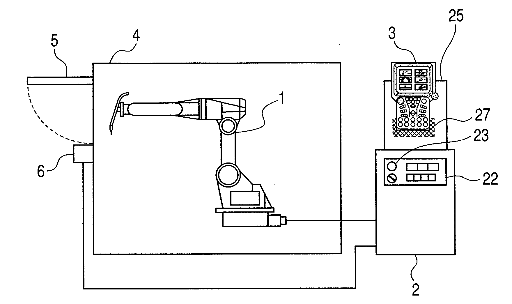
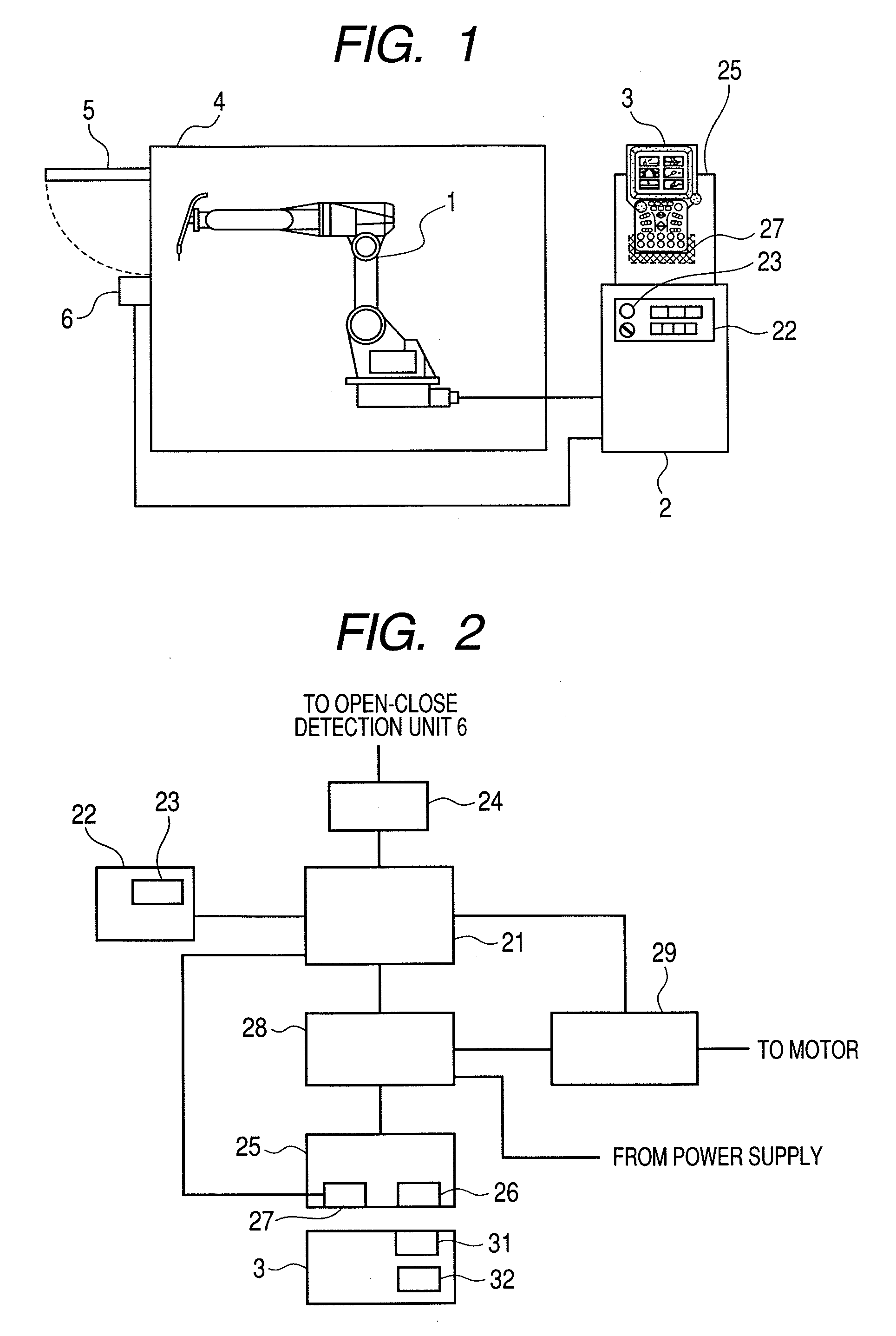
[0027]FIG. 1 is a configuration diagram of a robot system of an embodiment of the invention. In the figure, numeral 1 denotes a robot and numeral 2 denotes a robot controlling unit for controlling the robot 1. Numeral 3 denotes a teaching unit for mutually transmitting and receiving information with the robot controlling unit 2 by wireless connection. An operating range of the robot 1 is surrounded by a safety protective fence 4. A safety protective fence door 5 is provided at an exit / entrance in the safety protective fence 4. An open-close state of the safety protective fence door 5 is detected by an open-close detecting unit 6. An opening signal or closure signal is outputted to the robot controlling unit 2. A control section 22 which has an activation switch 23 for a selection of a teaching mode or a repeat mode and an operation program is provided on a control panel of the robot controlling unit 2. The control section 22 may be separated from the robot controlling unit 2 to be m...

embodiment 2

[0037]According to Embodiment 1, although the teaching unit 3 which is disposed on the feeding unit 25 is combined with the robot controlling unit 2, the teaching unit present signal is outputted. In Embodiment 2, this problem will be avoided.

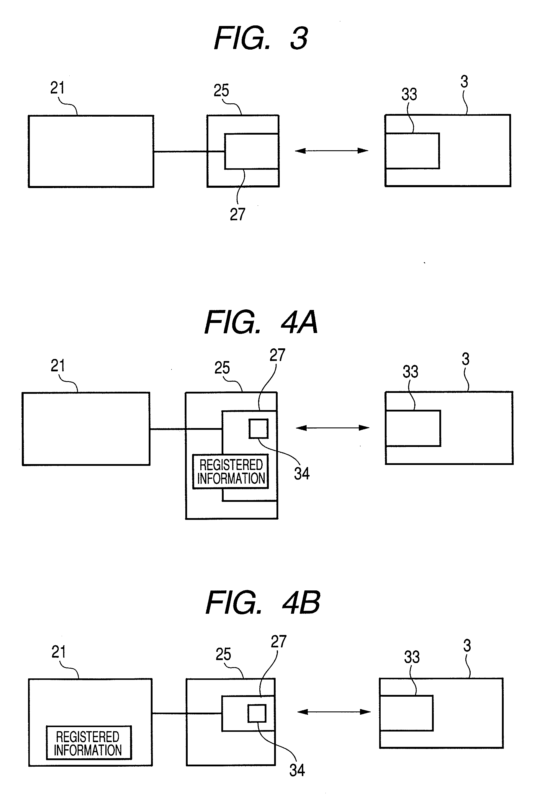
[0038]FIG. 3 is a block diagram showing another embodiment of a teaching unit detection device. In the figure, reference numerals like to those of Embodiment 1 have configurations corresponding thereto, and the description thereof will partially be omitted. In the figure, a teaching unit 3 includes an RDIF tag 33 which is embedded or affixed to a predetermined position on a case, and when the teaching unit 3 is disposed in a predetermined position on a feeding unit 25, the feeding unit 25 includes a teaching unit detection device 27 for reading information in the RDIF tag 33 in a location which confronts the RDIF tag 33 of the teaching unit 3.

[0039]Intrinsic information which identifies a robot controlling unit 2 which connects the teaching uni...


PUM


Abstract

The safety of an operator which may be endangered by an erroneous instruction by the operator or a robot control system is ensured by making more stringent a condition regarding the separation of the operator from the vicinity of a robot when an operation program of the robot is activated. An interlock to which a condition regarding activation of the operation program of the robot is added is provided in a feeding unit which is connected to a robot controlling unit by wireless connection for charging a teaching unit, so as to provide a robot system which improves the safety of the operator.

Description

TECHNICAL FIELD[0001]The present invention relates to a power feeding apparatus to a teaching unit in a robot system in which information is transmitted using wireless connection between a robot controlling unit and the teaching unit and more particularly to an interlock for activating an operation program for an operation carried out by a robot.BACKGROUND ART[0002]In a teaching playback type robot, the registration of predetermined positions and input / output control commands of operations of operation jigs is implemented by operating the robot by operating a portable teaching unit (also referred to as a pendant) in a teaching mode of the robot using an operation procedure carried out by the robot as an operation program.[0003]Since this teaching unit is controlled by an operator who holds it, weight and size reductions have been taken into consideration. However, to receive a power supply from the robot controlling unit and transmit and receive signals, the teaching unit has been c...

Claims


Application Information

Patent Timeline
IPC IPC(8): B25J9/16B25J11/00
CPCG05B2219/40197B25J9/1676
Inventor AKASHI, AKIRATANAKA, MICHIHARU
Owner YASKAWA DENKI KK
Why Eureka
Try Eureka