Slitter tool for cutting a tubular sheath of a guide catheter

Active Publication Date: 2009-03-19
SORIN CRM
View PDF14 Cites 72 Cited by
  • Summary
  • Abstract
  • Description
  • Claims
  • Application Information

AI Technical Summary

Benefits of technology

[0021]It is an object of the present invention to palliate all these difficulties, by proposing a cutting tool of the slitter type which,

Problems solved by technology

The insertion of the latter type of leads, carried out through endocavitary approaches, is a particularly tricky intervention, taking into account the difficult access to the coronary sinus entrance via the right atrium, and also the required accuracy for the pacing sites once the lead is guided to its desired position and immobilized within the coronary network.
Once the lead is in place, the guide-catheter needs to be extracted, and the extraction procedure is tricky because the lead must not be displaced, or its position or orientation altered as a result of the extraction.
One other difficulty of this extraction step is due to the presence of the electrical connector, at the proximal end of the lead.
However, cutting of such a sheath along its whole length leads to a weakness and a lower rigidity of the guide-catheter, with a risk of folding and lower transmission of efforts (applied forces) during its setting up preparatory to an intervention event.
This method however leads to an increasing number of steps required for setting up and assembling the different elements, and also renders the intervention procedure more complicated.
One of the main difficulties inherent to this method, lies in the risk of a lead displacement during the catheter extraction.
This implies a significantly longer intervention time, particularly with left ventricular leads,

Method used


Image

  • Slitter tool for cutting a tubular sheath of a guide catheter
  • Slitter tool for cutting a tubular sheath of a guide catheter
  • Slitter tool for cutting a tubular sheath of a guide catheter

Examples


Embodiment Construction

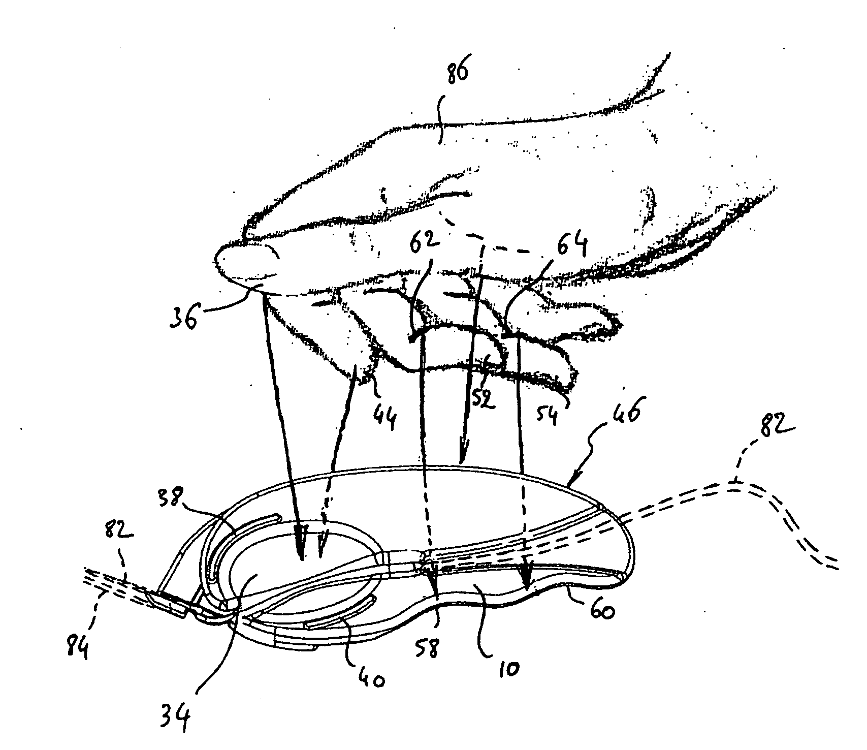
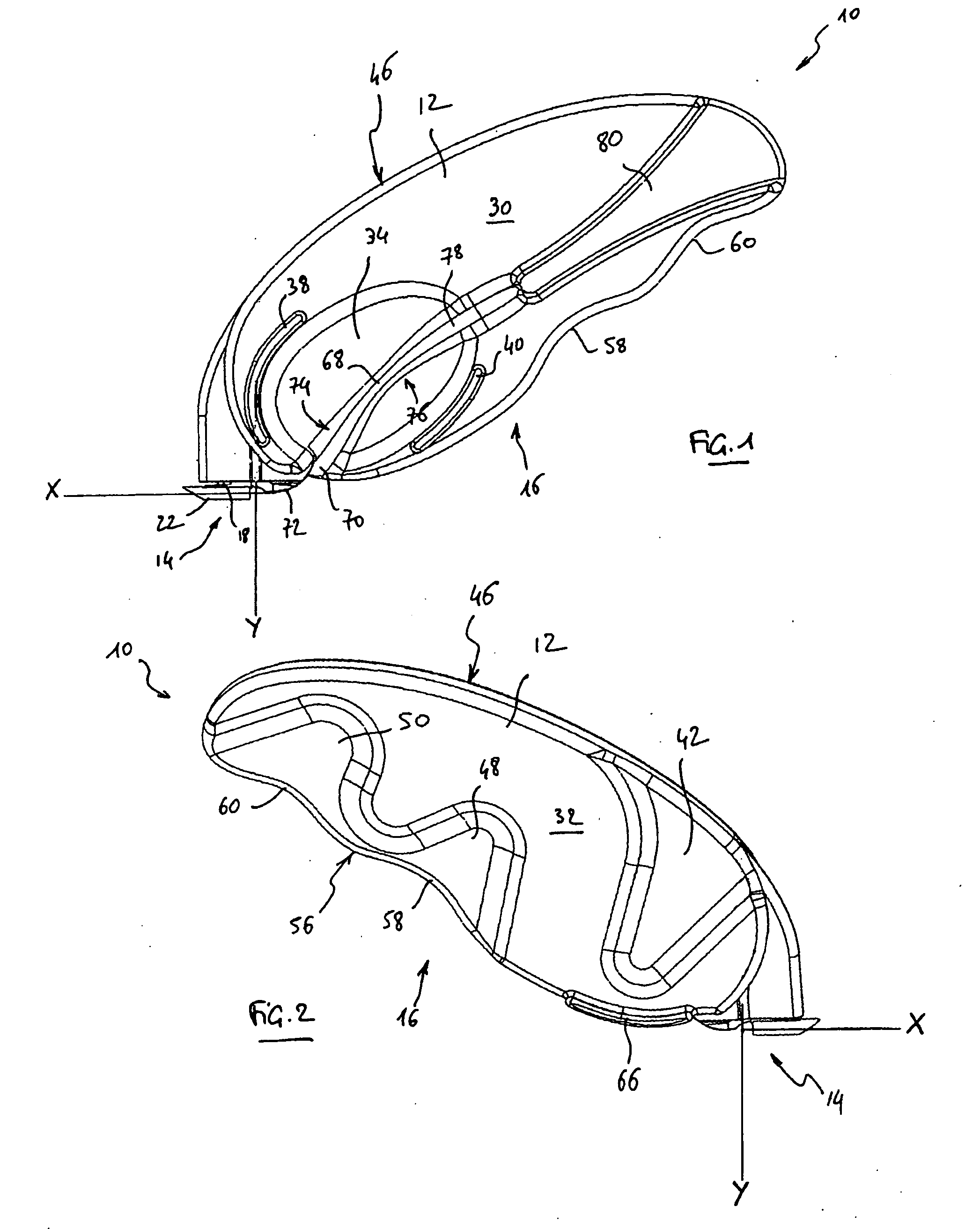
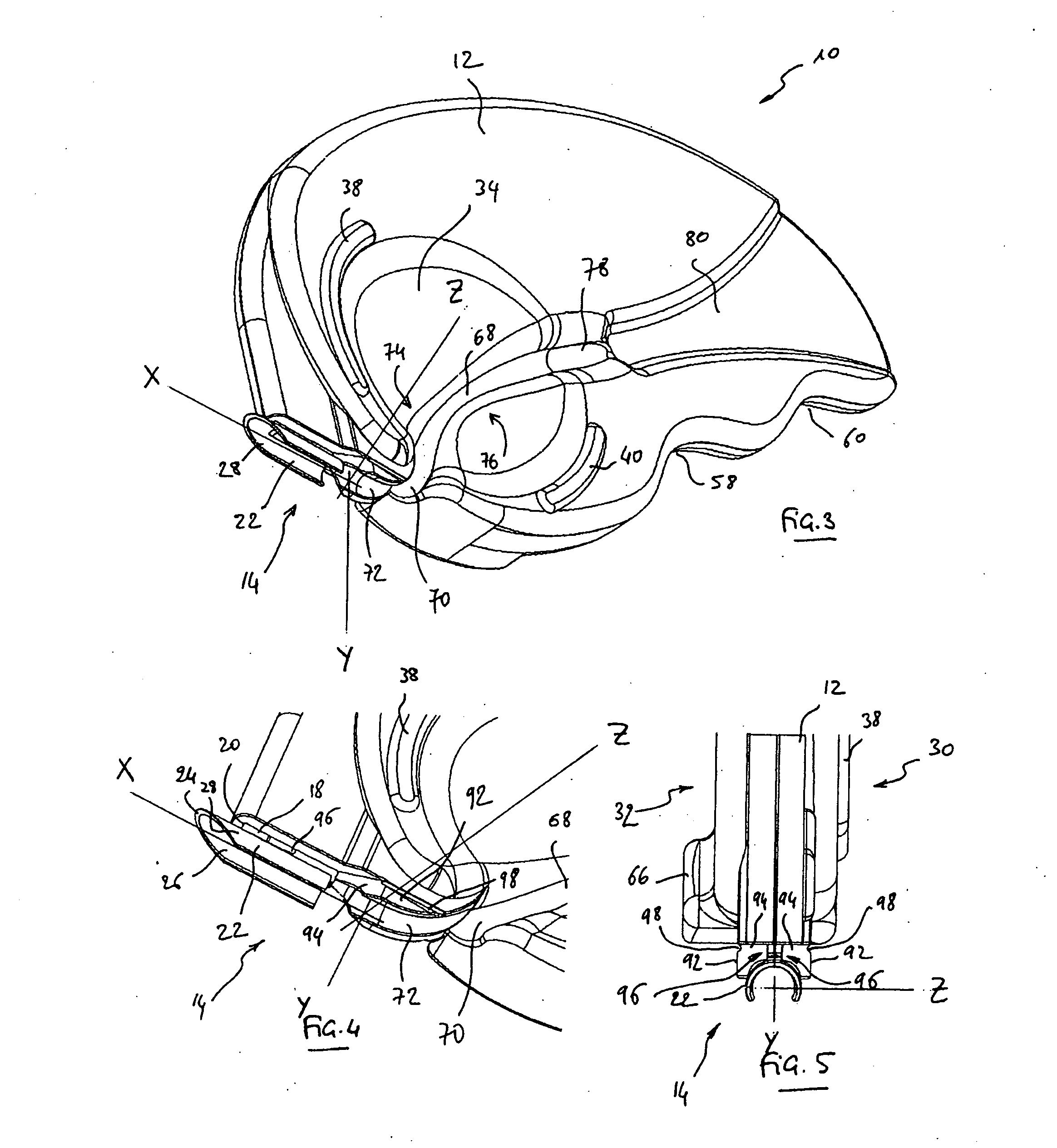
[0047]One will now describe an embodiment of the slitter tool according to a preferred embodiment of the present invention. With reference to the figures, reference 10 generally corresponds to the slitting tool or “slitter” tool of the present invention. Tool 10 comprises a blade holder body 12 with a roughly flattened shape, comprising a cutting area 14 and a prehension area 16.

[0048]Tool 10, for example, presents the following typical overall dimensions: length (the longer longitudinal dimension of the tool) of 65 to 100 mm, width (the longer transversal dimension) of 35 to 40 mm, and thickness of 5 to 6 mm. Of course, these dimensions are exemplary, and in no way limitative; and one of ordinary skill in the art will understand that the size of tool 10 must be such that the tool may be handled in the inside of a surgeon's hand, and not merely between the thumb and the forefinger, as it is the case with the various slitter tools that have been proposed by the prior art so far.

[0049...


PUM

PropertyMeasurementUnit
Distanceaaaaaaaaaa
Distanceaaaaaaaaaa
Distanceaaaaaaaaaa

Abstract

A tool for cutting or slitting the tubular sheath of a guide-catheter in the presence of a lead placed in this sheath. The tool (10) has a flattened, substantially planar blade holder body (12) with a cutting area (14) and a prehension area (16). The cutting area has a blade (18) and a tubular guide (22) receiving the lead for isolating it from the guide-catheter. The prehension area (16) has on a first side (30) an area for receiving the thumb and a lead holding pathway (68) spreading in the continuation of the tubular guide following an overall orientation forming an angle with this guide. The thumb reception area has a concave footprint (34) crossed through and through by the lead holding pathway (68), which spreads in the prehension area following an “S” shaped curve having a first curved area (74) and a second counter-curved area (76). The minimal distance between the blade (18) and the contour of the first footprint (34) is to the most equal to 15-20 mm.

Description

FIELD OF THE INVENTION[0001]The present invention is related to the implantation of intracorporal leads, more particularly leads for cardiac sensing / pacing that are usually associated with “active implantable medical devices” as such devices are defined by the Jun. 20, 1990 directive of the Counsel of European communities, and more specifically to implantable devices for cardiac pacing, resynchronization, cardioversion and / or defibrillation.BACKGROUND OF THE INVENTION[0002]Cardiac leads may be endocardial leads, such as leads for sensing / pacing in right heart cavities, or leads introduced in the coronary network, notably leads comprising an electrode positioned in front of a left cavity of the myocardium.[0003]The insertion of the latter type of leads, carried out through endocavitary approaches, is a particularly tricky intervention, taking into account the difficult access to the coronary sinus entrance via the right atrium, and also the required accuracy for the pacing sites once...

Claims


Application Information

Patent Timeline
IPC IPC(8): B26B27/00
CPCA61M25/06A61M2025/0675A61M25/0668
Inventor SHAN, NICOLASOLLIVIER, JEAN-FRANCOIS
Owner SORIN CRM
Why Eureka
Try Eureka