Acceleration sensor

a sensor and acceleration technology, applied in the field of acceleration sensors, can solve the problems of insufficient acceleration detection accuracy, difficult to dope phosphorus or boron at each location, and the voltage equivalent to those output when acceleration is applied, so as to reduce the size of the acceleration sensor, reduce the displacement of the beam portion caused by the displacement of the weight portion, and reduce the effect of acceleration sensor siz

Inactive Publication Date: 2009-03-19
MURATA MFG CO LTD
View PDF11 Cites 6 Cited by
  • Summary
  • Abstract
  • Description
  • Claims
  • Application Information

AI Technical Summary

Benefits of technology

[0020]According to preferred embodiments of the present invention, the frame-shaped beam portion is preferably attached to the base so as to be supported on two sides with the support portions that extend in the X-axis direction on either side of the beam portion. Therefore, when, for example, the base is distorted by thermal stress, the distortion in the Y-axis direction (for example, in the longitudinal direction) is absorbed by the deflection of the support portions. With respect to the distortion in the X-axis direction (for example, in the transverse direction), an overall displacement caused by the distortion is relatively small. In addition, portions of the beam portion separated from the regions at which the support portions and the connecting portions are connected to the beam portion are deformed due to the distortion in the X-axis direction, so that the distortion in the X-axis direction can be absorbed. Therefore, according to preferred embodiments of the present invention, the beam portion can be prevented from being distorted in the regions at which the support portions and the connecting portions are connected to the beam portion or in regions adjacent thereto.
[0021]In addition, the X-axis-direction acceleration detection unit, the Y-axis-direction acceleration detection unit, and the Z-axis-direction acceleration detection unit arranged to detect the accelerations based on the distortion of the beam portion are preferably provided on the beam portion. The acceleration detection units are preferably provided on the beam portion in regions at which distortion caused by distortion of the base due to thermal stress or other external forces is zero or extremely small. Therefore, according to preferred embodiments of the present invention, the occurrence of false detection of acceleration due to the distortion of the base caused by thermal stress can be effectively suppressed. The false detection of acceleration means a situation in which even when no acceleration is applied, an acceleration is detected by the X-axis-direction acceleration detection unit, the Y-axis-direction acceleration detection unit, or the Z-axis-direction acceleration detection unit due to the distortion of the base caused by thermal stress.
[0022]In addition, according to preferred embodiments of the present invention, the frame-shaped beam portion is preferably attached to the base so as to be supported on two sides, and the weight portions are preferably retained by the beam portion in a cantilever state. Thus, the structure is simple. Therefore, the size of the acceleration sensor can be reduced.
[0023]In addition, the weight portions are preferably connected to the frame-shaped beam portion in a cantilever manner. Therefore, the displacements of the weight portions caused by the accelerations are relatively large. Accordingly, the deflection of the beam portion caused by the displacements of the weight portions is increased, and the acceleration detection sensitivity can be increased.
[0024]The Y-axis-direction acceleration detection unit is preferably disposed near the distal ends of the Y-axis-direction extending portions extending in the Y-axis direction from the locations at which the frame-shaped beam portion is supported by the support portions. In the region in which the Y-axis-direction acceleration detection unit is disposed, the density of wiring connected to the acceleration detection unit can be reduced. Therefore, the beam width, for example, can be reduced. By reducing the width of the Y-axis-direction extending portions at the distal ends thereof, the acceleration detection sensitivity in the Y-axis direction can be increased. By comparison, the Z-axis-direction acceleration detection unit is preferably disposed near the proximal ends of the Y-axis-direction extending portions. In the region in which the Z-axis-direction acceleration detection unit is disposed, the wiring density is increased. Therefore, the beam width of the Y-axis-direction extending portions at the proximal ends thereof cannot be set as small as that of the Y-axis-direction extending portions at the distal ends thereof. However, the bending moment is at a maximum at the proximal ends of the Y-axis-direction extending portions. Therefore, the acceleration detection sensitivity in the Z-axis direction can be increased to a level that is substantially equivalent to that in the Y-axis direction by, for example, increasing the size of the weights in the Y-axis direction.
[0025]Therefore, according to preferred embodiments of the present invention, even when the elements provided on the base are arranged in a low-profile structure (i.e., even when the thickness in the Z-axis direction is reduced), an acceleration sensor having a high, uniform acceleration detection sensitivity in the X, Y, and Z axis directions can be obtained.

Problems solved by technology

As a result, there is a risk that voltages equivalent to those output when accelerations are applied will be output from the bridge circuits shown in FIGS. 17S to 17V even when no acceleration is applied.
In this case, if the locations at which the resistance elements are to be arranged are separate from each other, it is difficult to dope phosphorus or boron uniformly at each location.
Therefore, the accuracy of acceleration detection cannot be sufficiently increased.

Method used


Image

  • Acceleration sensor
  • Acceleration sensor
  • Acceleration sensor

Examples


Embodiment Construction

[0064]Preferred embodiments of the present invention will be described below with reference to the drawings.

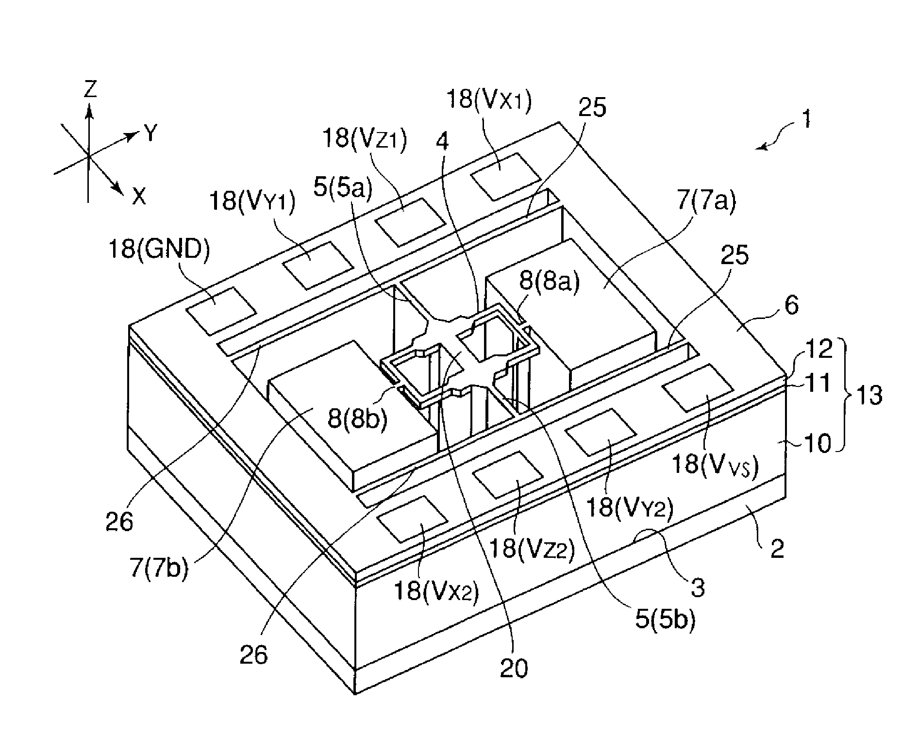
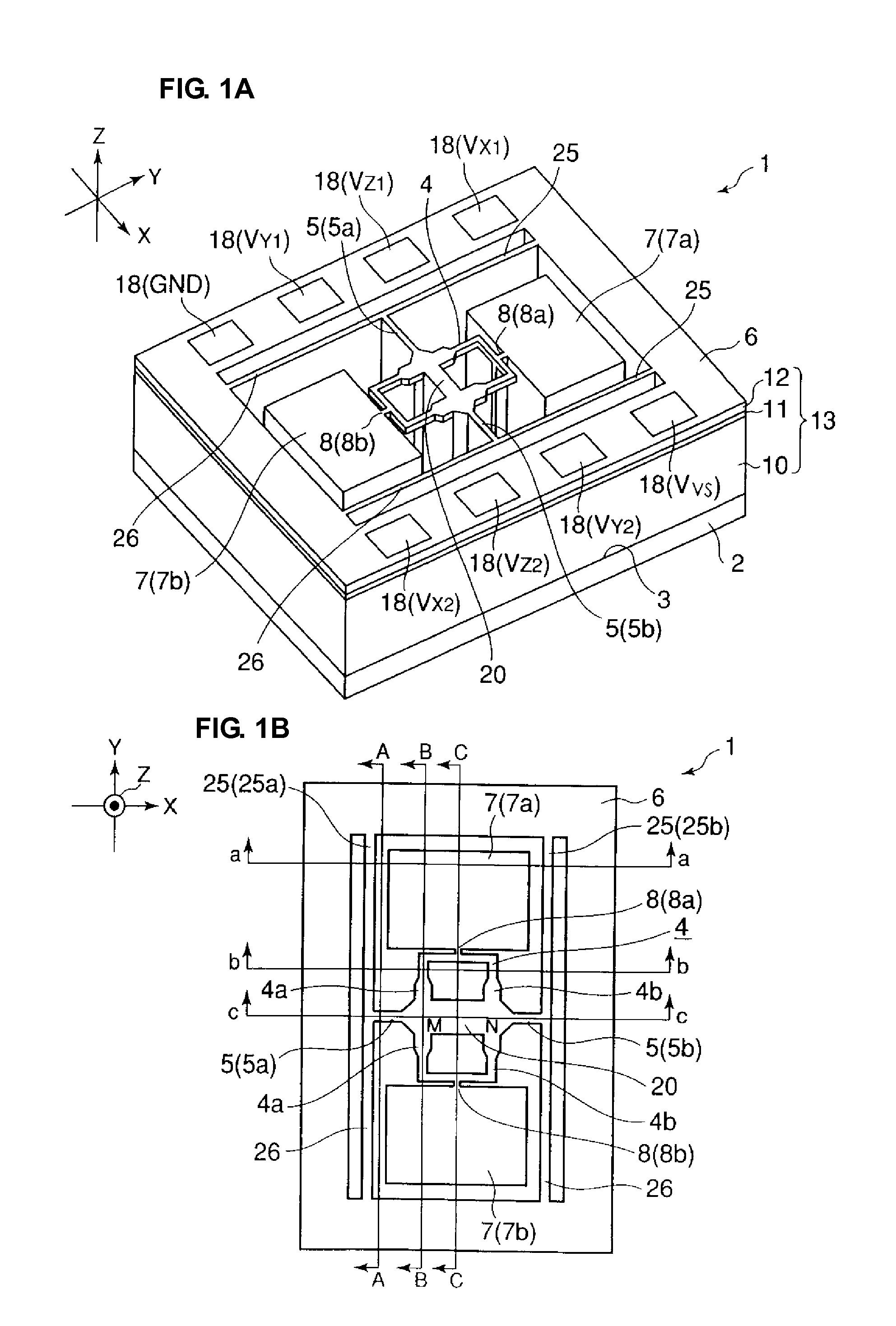
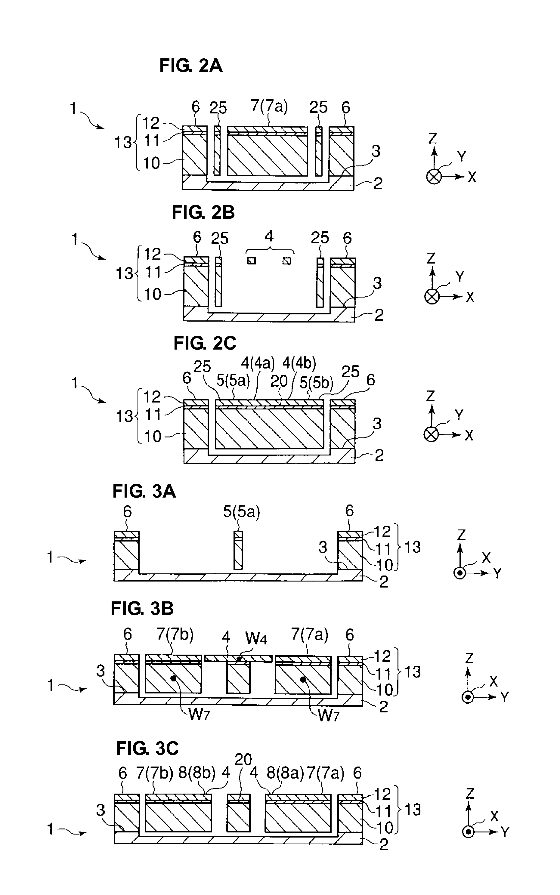
[0065]FIG. 1A is a schematic perspective view illustrating an acceleration sensor according to a preferred embodiment of the present invention. FIG. 1B is a schematic plan view illustrating the acceleration sensor shown in FIG. 1A. In FIG. 1B, electrode pads denoted by reference numeral 18 in FIG. 1A are omitted. FIG. 2A is a schematic sectional view of FIG. 1B taken along line a-a. FIG. 2B is a schematic sectional view of FIG. 1B taken along line b-b. FIG. 2C is a schematic sectional view of FIG. 1B taken along line c-c. In addition, FIG. 3A is a schematic sectional view of FIG. 1B taken along line A-A. FIG. 3B is a schematic sectional view of FIG. 1B taken along line B-B. FIG. 3C is a schematic sectional view of FIG. 1B taken along line C-C.

[0066]An acceleration sensor 1 according to the present preferred embodiment is capable of detecting accelerations in three axial direct...


PUM


Abstract

An acceleration sensor includes a frame-shaped beam portion disposed above an XY substrate surface of a base in a floating state and a beam-portion supporting/fixing unit arranged to attach the beam portion to the base with support portions so as to be supported on two sides. The acceleration sensor also includes weight portions disposed above the XY substrate surface of the base in a floating state and connecting portions for attaching the weight portions to the beam portion in a cantilever state. The weight portions are movable in three axial directions including an X-axis direction, a Y-axis direction, and a Z-axis direction when the beam portion is deflected. The beam portion is provided with an X-axis-direction acceleration detection unit arranged to detect an acceleration in the X-axis direction, a Y-axis-direction acceleration detection unit arranged to detect an acceleration in the Y-axis direction, and a Z-axis-direction acceleration detection unit arranged to detect an acceleration in the Z-axis direction. The Z-axis-direction acceleration detection unit is disposed near proximal ends of Y-axis-direction extending portions of the beam portion, and the Y-axis-direction acceleration detection unit is disposed near distal ends of the Y-axis-direction extending portions.

Description

BACKGROUND OF THE INVENTION[0001]1. Field of the Invention[0002]The present invention relates to an acceleration sensor capable of detecting accelerations in three axial directions including an X-axis direction, a Y-axis direction, and a Z-axis direction which are perpendicular or substantially perpendicular to one another.[0003]2. Description of the Related Art[0004]FIG. 16 is a schematic perspective view illustrating an example of an acceleration sensor (see, for example, Japanese Unexamined Patent Application Publication No. 2002-296293). An acceleration sensor 40 shown in FIG. 16 includes a frame portion 41 and a columnar weight member 42 disposed at a central portion of the frame portion 41. X-axis-direction beam portions 43a and 43b extend in the X-axis direction from either end of the weight member 42 in the X-axis direction toward the frame portion 41. Y-axis-direction beam portions 44a and 44b extend in the Y-axis direction from either end of the weight member 42 in the Y-a...

Claims


Application Information

Patent Timeline
Patent Type & Authority Applications(United States)
IPC IPC(8): G01P15/00G01P15/12G01P15/18H01L29/84
CPCG01P15/18G01P15/123G01P2015/084G01P15/12G01P15/125
Inventor MOCHIDA, YOICHI
Owner MURATA MFG CO LTD
Why Eureka
Try Eureka