
Rotary atomizer head type paining machine

a rotary atomizer and coating machine technology, applied in the direction of electrostatic spraying apparatus, coatings, movable spraying apparatus, etc., can solve the problems of difficult to wash paint, troublesome and time-consuming job of mounting or dismantling a rotary atomizing head on or off a rotational shaft, and needing to turn the stopper pin

Inactive Publication Date: 2009-03-19
ABB IND
View PDF1 Cites 11 Cited by
  • Summary
  • Abstract
  • Description
  • Claims
  • Application Information

AI Technical Summary

Benefits of technology

[0014]It is another object of the present invention to provide a rotary atomizing head type coating machine which is arranged to lock a rotational shaft at the time of mounting or dismantling a rotary atomizing head, without applying unduly large radial loads to guarantee higher quality of coatings and higher operational reliability as well.
[0037]Therefore, even if operator's hands are off the rotatable ring, the rotational shaft can be retained fixedly in fixed state, permitting to carry out the mounting or dismantling work of the rotary atomizing head in an efficient manner.

Problems solved by technology

For fixing the rotational shaft, however, the stopper pin needs to be turned for many times. That is to say, mounting or dismantling a rotary atomizing head on or off a rotational shaft has been a troublesome and time-consuming job.
Therefore, paint tends to deposit on a protruded portion of the stopper pin, coupled with a problem that it is difficult to wash away paint which has gotten into a gap space between the stopper pin and the housing.
Defoliation of part of a paint deposit on the stopper pin can result in a coating defect or defects which will impair the quality of coatings and reliability of the machine as well.
Exertion of such a radial load on the rotational shaft, however, may result in a damage to a turbine or bearing of the air motor or bending deformation of the rotational shaft.
Especially in the case of recent rotary atomizing head type coating machines in which a rotary atomizing head is put in high speed rotation as high as 3,000 to 100,000 rpm, a slight damage or deformation could pose detrimental effects on the quality of coated products.

Method used


Image

  • Rotary atomizer head type paining machine
  • Rotary atomizer head type paining machine
  • Rotary atomizer head type paining machine

Examples


first embodiment

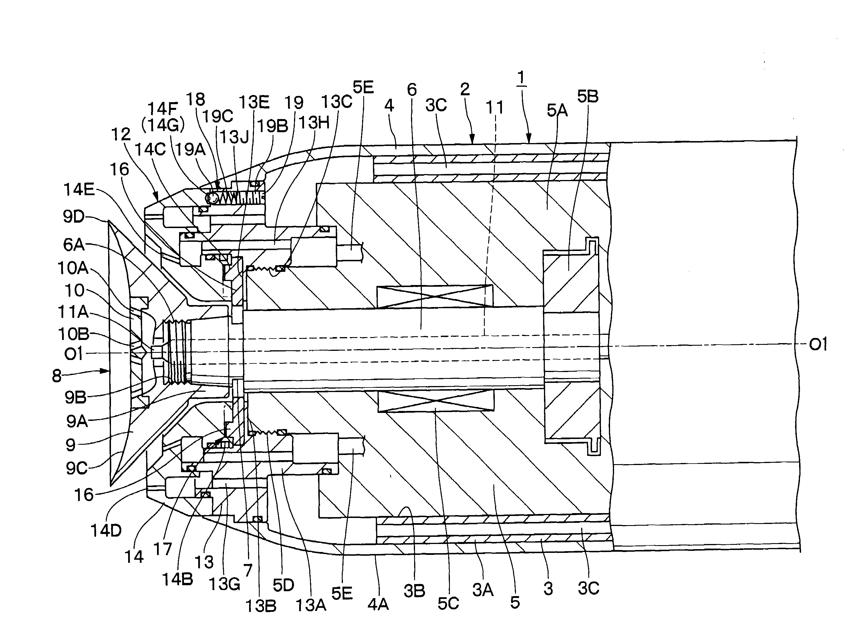
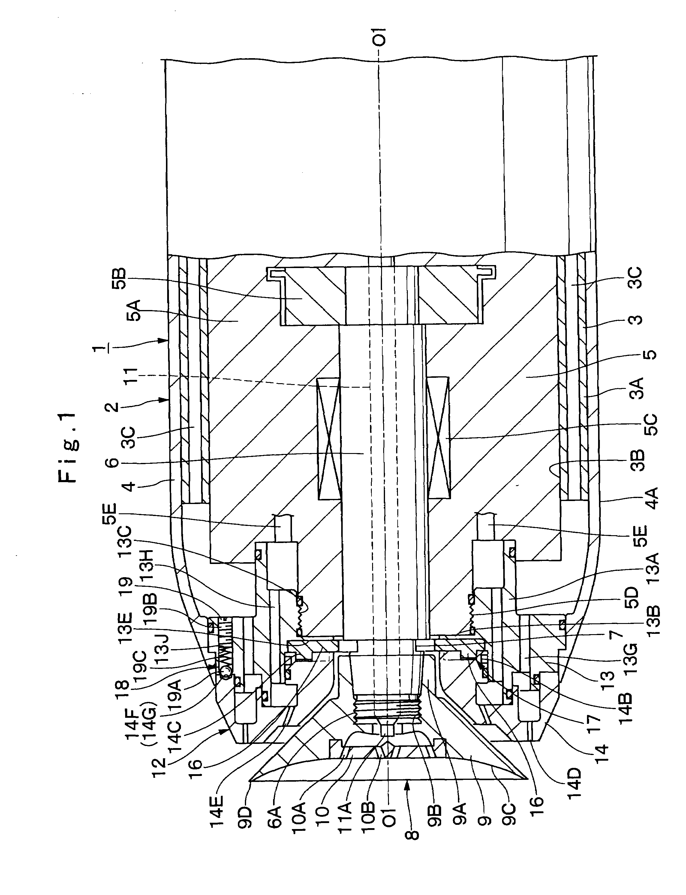
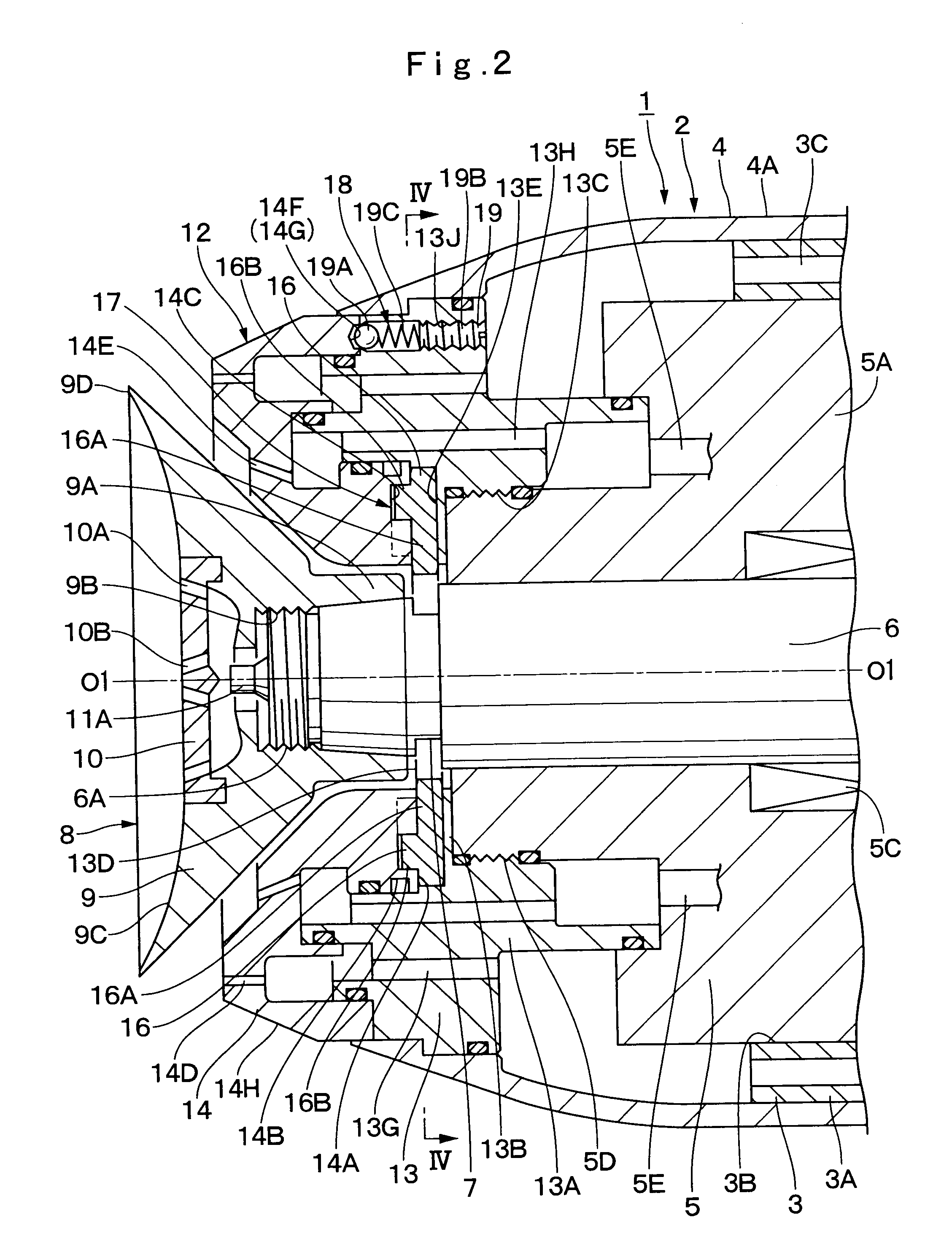
[0054]Referring first to FIGS. 1 through 8, there is shown the present invention.

[0055]In FIG. 1, indicated at 1 is a rotary atomizing head type coating machine according to a first embodiment of the invention. This coating machine 1 is attached, for example, to a distal end of an arm (not shown) of a coating robot, a reciprocator or the like. The rotary atomizing head type coating machine 1 is largely constituted by a housing 2, an air motor 5, a rotational shaft 6, coupling portions 7, a rotary atomizing head 8, a feed tube 11 and a shaping air ring 12, which will be described hereinafter.

[0056]Denoted at 2 is a housing which defines an outer configuration of the coating machine 1. This housing 2 is composed of an inner main housing body 3, and an outer cover 4. In this instance, the main housing body 3 is provided with a tubular portion 3A on the front side, internally defining a hollow motor receptacle cavity 3B to accommodate an air motor 5 in a fit-in fashion. A plural number ...

second embodiment

[0111]In FIG. 9, indicated at 21 are a couple of coupling portions which are provided on a fore end portion of the rotational shaft 6 in the These coupling portions 21 are each in the form of a bottomed round hole, and, as shown in FIG. 12, are gripped and engaged by slid pins 28 to fix the rotation of the rotational shaft 6 on the center axis O1-O1.

[0112]Indicated at 22 is a shaping air ring according to the second embodiment, which is located on the front side of the housing 2. Substantially in the same way as the shaping air ring 12 in the first embodiment, this shaping air ring 22 is adapted to spurt shaping air forward toward the rotary atomizing head 8 to put sprayed paint particle in a desired spray pattern. Further, the shaping air ring 22 also has a function of fixing and locking the rotational shaft 6 against rotation at the time of mounting or dismantling the rotary atomizing head 8.

[0113]Further, similarly to the shaping air ring 12 in the first embodiment, the shaping ...


PUM


Abstract

A coupling portion is provided on an outer peripheral side of a rotational shaft, a stationary ring is mounted on a fore end portion of an air motor, a rotatable ring is rotatably attached to a stationary ring, and slide plates are provided between the stationary ring and the rotatable ring movably in radially inward and outward directions of the rotational shaft. A slider shift mechanism provided on the stationary ring and the rotatable ring brings each slide plate into and out of engagement with the coupling portions in step with a rotational movement of the rotatable ring. Thus, for locking the rotational shaft in a fixed state, an operator grips and turns the rotatable ring with one hand to engage the slide plates with the coupling portions by the slider shift mechanism. In this state, a rotary atomizing head can be mounted on or dismantled from the rotational shaft.

Description

TECHNICAL FIELD[0001]This invention relates to a rotary atomizing head type coating machine suitable for use, for example, in painting vehicle bodies, furniture surfaces, electric appliances and the like.BACKGROUND ART[0002]Generally, because of high paint deposition efficiency and higher finish quality, rotary atomizing head type coating machines have been resorted to in painting vehicle bodies, furniture surfaces and electric appliances. For example, a rotary atomizing head type coating machine is largely composed of a tubular housing which is mounted on a distal end of an arm of a coating robot, an air motor for driving at a high speed a rotational shaft which is accommodated in the housing, a bell- or cup-shaped rotary atomizing head which is mounted on a fore end portion of the rotational shaft on the front side of the housing, and a paint passage for circulation of paint to be supplied to the rotary atomizing head.[0003]In a rotary atomizing head type coating machine of this s...

Claims


Application Information

Patent Timeline
IPC IPC(8): B05B3/02
CPCB05B3/1014B05B3/1035B05B3/1092B05B3/1064B05B3/1042B05B5/04B05B3/10
Inventor YASUDA, SHINICHIMATSUURA, TOSHIFUMI
Owner ABB IND
Learn More