
Dual function umbrella

a dual-functional, umbrella technology, applied in umbrellas, walking sticks, clothing, etc., can solve the problems of easy scraping and scratching of users in the process of use, and achieve the effect of reducing abrasion of rope, and smooth and efficient tightening and loosening of rop

Inactive Publication Date: 2009-03-19
ZHAO STEPHEN
View PDF19 Cites 6 Cited by
  • Summary
  • Abstract
  • Description
  • Claims
  • Application Information

AI Technical Summary

Benefits of technology

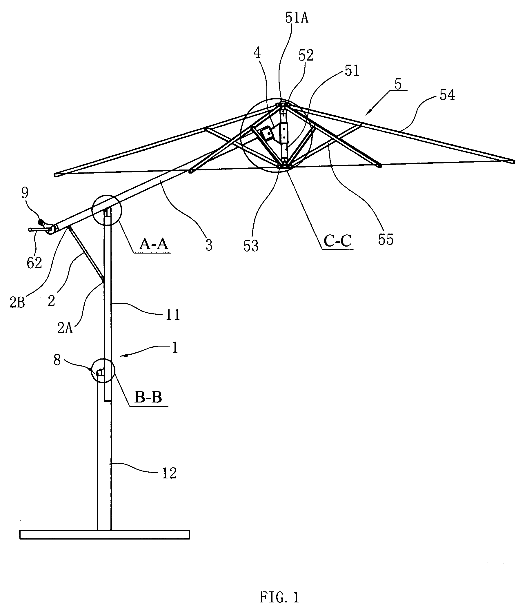
[0007]The crank mechanism may adopt existing umbrella features, such as the manual and electric crank mechanisms published in patent documents such as mentioned in the above background references. However, to obtain a simpler structure, and to realize smooth and efficient tightening and loosening of the rope, the crank mechanism may include a rope shaft at the bottom end of the cross bar, a handle for driving the rotation of the rope shaft, and a holder pulley and rope inside the central umbrella rod of the umbrella holder. One end of the rope may be fixed to the rope shaft and the other end may pass through the cross bar to then enter into the central umbrella rod and pass over the holder pulley therein to then be fixed to the moveable umbrella bracket. This may allow tighten the rope by rotating the rope shaft through the handle to cause the moveable umbrella bracket to rise relative to the central umbrella rod to prop up the supporting ribs and umbrella ribs and thus open up the umbrella fabric. When the handle may be rotated in the opposite direction to loosen the rope, the moveable umbrella bracket as well as the supporting ribs and umbrella ribs may contract and fold due to deadweight, and the umbrella fabric may also contract to relieve the stretching and to contract the umbrella fabric. To reduce abrasion of the rope, and to ensure that the rope may move correctly through the end of the cross bar and may be routed over the holder pulley inside the central umbrella rod, a pair of locating pulleys may be positioned inside the top end of the cross bar and the rope may be routed between the pair of locating pulleys. The locating pulleys may keep the rope from contacting the inner wall of the cross bar directly and from binding in the holder pulley inside the central umbrella rod. To aid users to pull and control the cross bar more conveniently and more smoothly when switching between the vertical-supported and inclined-suspended positions for the umbrella, a handle may be attached at the bottom end of the cross bar. A steering unit may be positioned at the central umbrella rod and the top end of the cross bar may be pin-jointed to the steering unit for convenience of manufacture.
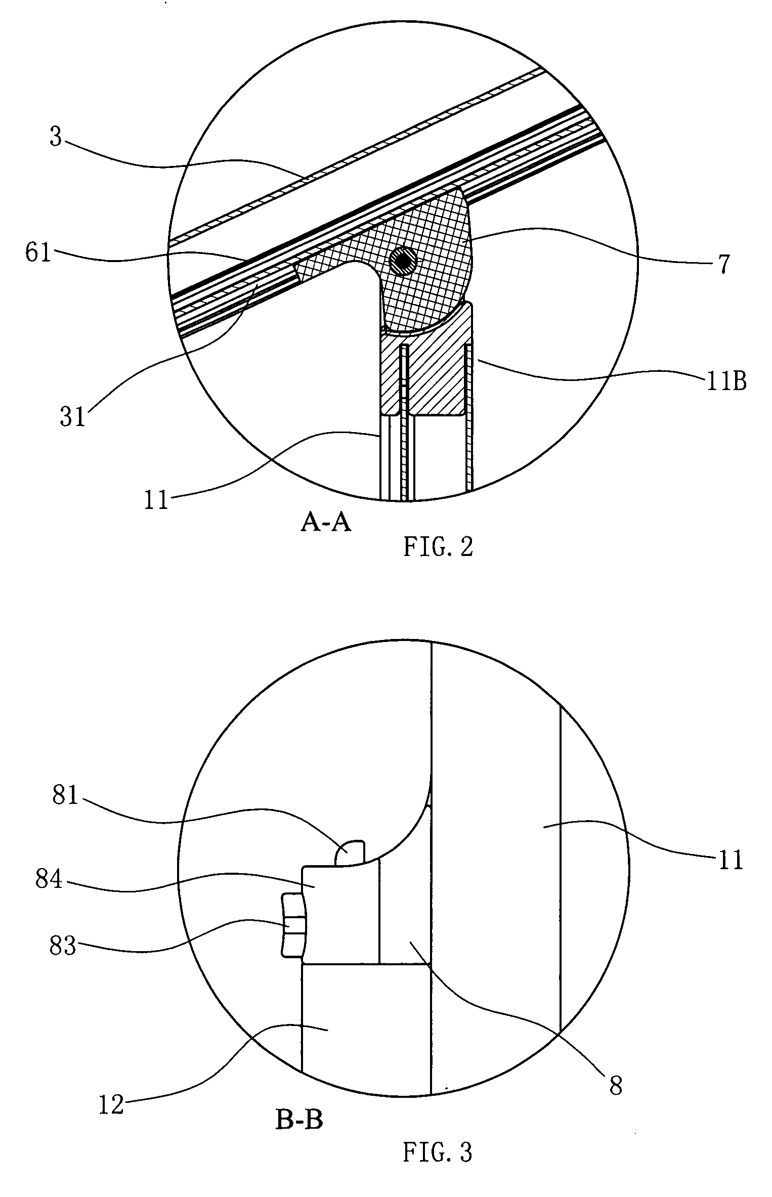
[0008]When the umbrella may be in the vertical-supported position, the frame column and the cross bar may be adjacent each other. In this position the bottom end of the cross bar may stick out at one side of the frame column, which may easily scrape and scratch users in the process of use. To reduce this possibility, the frame column may have a lower frame column and an upper frame column that may be inserted on the lower frame column. When the frame column and cross bar closely adjoin to each other, the external surface of the lower frame column may be flush with that of the cross bar and upper frame column. This structural combination of the cross bar and upper frame column may allow the cross bar, the upper frame column and the lower frame column to form an integral structure with a tidy and smooth appearance to provide users with a more functional device.

Problems solved by technology

In this position the bottom end of the cross bar may stick out at one side of the frame column, which may easily scrape and scratch users in the process of use.

Method used


Image

  • Dual function umbrella
  • Dual function umbrella
  • Dual function umbrella

Examples


Embodiment Construction

[0022]The following detailed description represents the best currently contemplated modes for carrying out the invention. The description is not to be taken in a limiting sense, but is made merely for the purpose of illustrating the general principles of the invention.

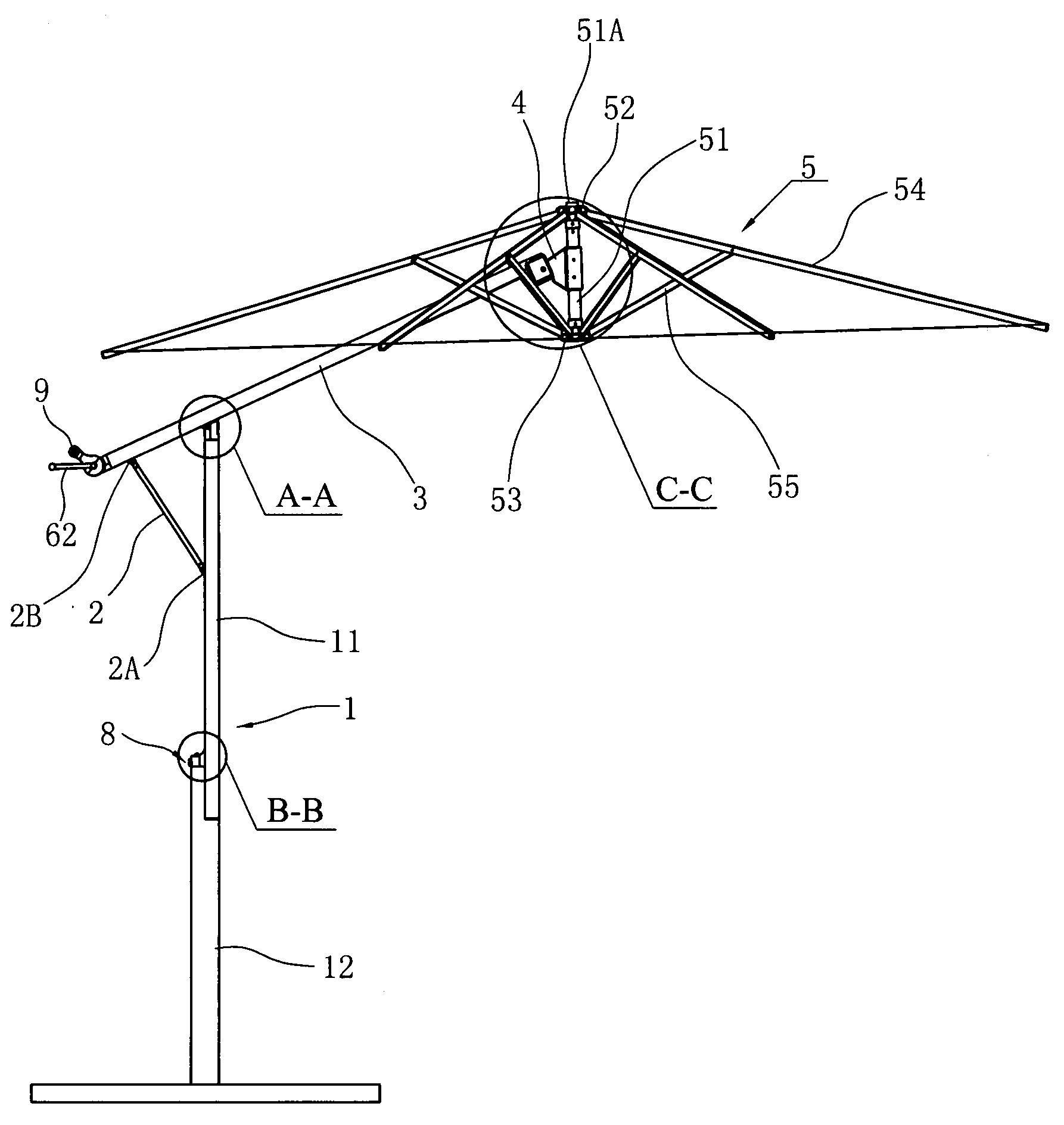
[0023]Referring to FIGS. 1 through 11, the dual-function umbrella 20 may have a vertical supported and an inclined suspended configuration or position and may have a frame column 1, a tilting bar 2, a cross bar 3, an umbrella holder 5 and a crank mechanism 6. The umbrella holder 5 may include a fixed umbrella bracket 52 fixed to a central umbrella rod 51, a moveable umbrella bracket 53 slidably disposed on the central umbrella rod 51, multiple umbrella ribs 54 with one end pin-jointed to the fixed umbrella bracket 52, and multiple supporting ribs 55 with one end pin-jointed to the moveable umbrella bracket 53 and the other end pin-jointed to the central part of a corresponding umbrella rib 54.

[0024]The frame column 1 m...


PUM


Abstract

The present invention involves umbrella devices and methods for dual-function umbrellas that may combine a vertical-supported and inclined-suspended umbrella in one structure. A dual-function umbrella that may have vertical supporting and incline suspending structure may have a frame column, umbrella holder and a crank mechanism to position the umbrella holder; the umbrella holder may include a fixed umbrella bracket, moveable umbrella bracket, multiple umbrella ribs with one end pin-jointed to the fixed umbrella bracket, and multiple supporting ribs with opposite ends pin-jointed to the central part of a corresponding umbrella rib and the moveable umbrella bracket. The dual-function umbrella may also have a tilting bar and a cross bar wherein the frame column may be equipped with a moveable locking gear for locking the bottom end of the cross bar. The crank mechanism may be positioned at the cross bar bottom end. Each end of the tilting bar may be pin-jointed to the middle part of the frame column and the lower part of the cross bar respectively. The top end of the cross bar may be pin-jointed to the middle part of the central umbrella rod, and the cross bar may have a slot on the lateral side corresponding to the frame column. Inside the slot there may be an embedded slide block, and the top end of the frame column may be pin-jointed to the slide block, such that the top end of the frame column slide block may move along the slot of and relative to the cross bar.

Description

BACKGROUND OF THE INVENTION[0001]This invention involves umbrellas, especially a kind of umbrella available to be used alternatively between a direct supporting and inclined position.[0002]Along with the growth in the living standard, people have participated in outdoor leisure activities more frequently. At leisure places including plazas, backyards, parks and beaches, etc. . . . umbrellas have already become a regular appliance, which has provided people with comfortable space for enjoying the shade. Umbrellas include vertical-supported and inclined-suspended umbrellas (also known as cantilever-type umbrellas). Vertical-supported umbrellas may have the same structure and principles as those of common umbrellas, mainly including a frame column, a fixed umbrella bracket fastened to the top end of the frame column, a moveable umbrella bracket equipped outside the middle part of the frame column, multiple supporting ribs, multiple umbrella ribs and an umbrella fabric stretched over th...

Claims


Application Information

Patent Timeline
IPC IPC(8): A45B11/00
CPCA45B17/00A45B23/00A45B2025/146A45B2023/0081A45B2023/0037
Inventor ZHAO, STEPHEN
Owner ZHAO STEPHEN
Learn More