
Heat sink assembly

Inactive Publication Date: 2009-03-19
LIAO WEN CHIH
View PDF6 Cites 11 Cited by
  • Summary
  • Abstract
  • Description
  • Claims
  • Application Information

AI Technical Summary

Benefits of technology

[0005]The objective of the present invention is to increase heat dissipation area and to improve heat dissipation efficiency of a heat pipe for dissipating heat more quickly and uniformly.
[0006]A heat sink assembly in accordance with the present invention increases heat dissipation area, improves heat dissipation efficiency and comprises a base, a core pipe, an outer pipe, a top cover and a working fluid. The base has a top surface. The core pipe is copper-silver alloy brazed securely on and protrudes from the top surface with an air-tight fit and comprises an inner surface, an outer surface, a wick, multiple holes and an open top. The wick is formed on the inner and outer surface. The outer pipe is copper-silver alloy brazed securely on and protrudes from the base concentrically around the core pipe and comprises an inner surface, an outer surface, a wick and an open top. The wick is formed on the inner surface. The holes are formed around the core pipe away from the base. The top cover is copper-silver alloy brazed securely on and closes the open tops of the core pipe and the outer pipe. The working fluid is pure water and is injected into the core pipe and the outer pipe in the presence of a vacuum.

Problems solved by technology

Without effective dissipation of the increased heat, reliability and life span of the associated electronic equipment will be adversely affected.
However, smaller electronic equipment size limits the number and size of fins that can be used to effectively dissipate heat generated by the electronic equipment.
As heat generated increases and size decreases in modern, high performance, high power electronic devices, the conventional heat pipe is not adequate to dissipate heat generated.

Method used


Image

  • Heat sink assembly
  • Heat sink assembly
  • Heat sink assembly

Examples


Embodiment Construction

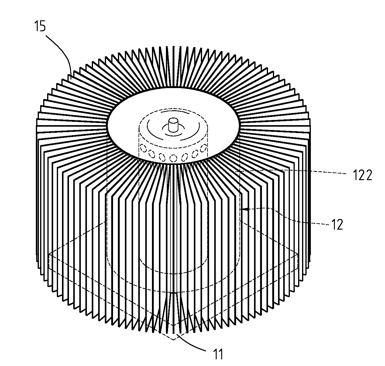
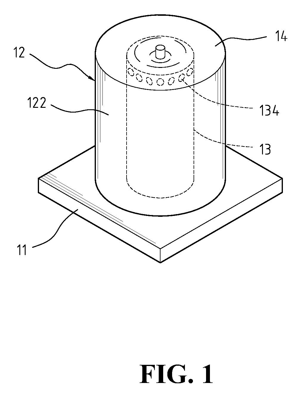
[0025]With reference to FIGS. 1, 3, 5 and 9, a heat sink assembly in accordance with the present invention comprises a base (11), a core pipe (13), an outer pipe (12), a top cover (14, 135), a working fluid and multiple optional fins (15).

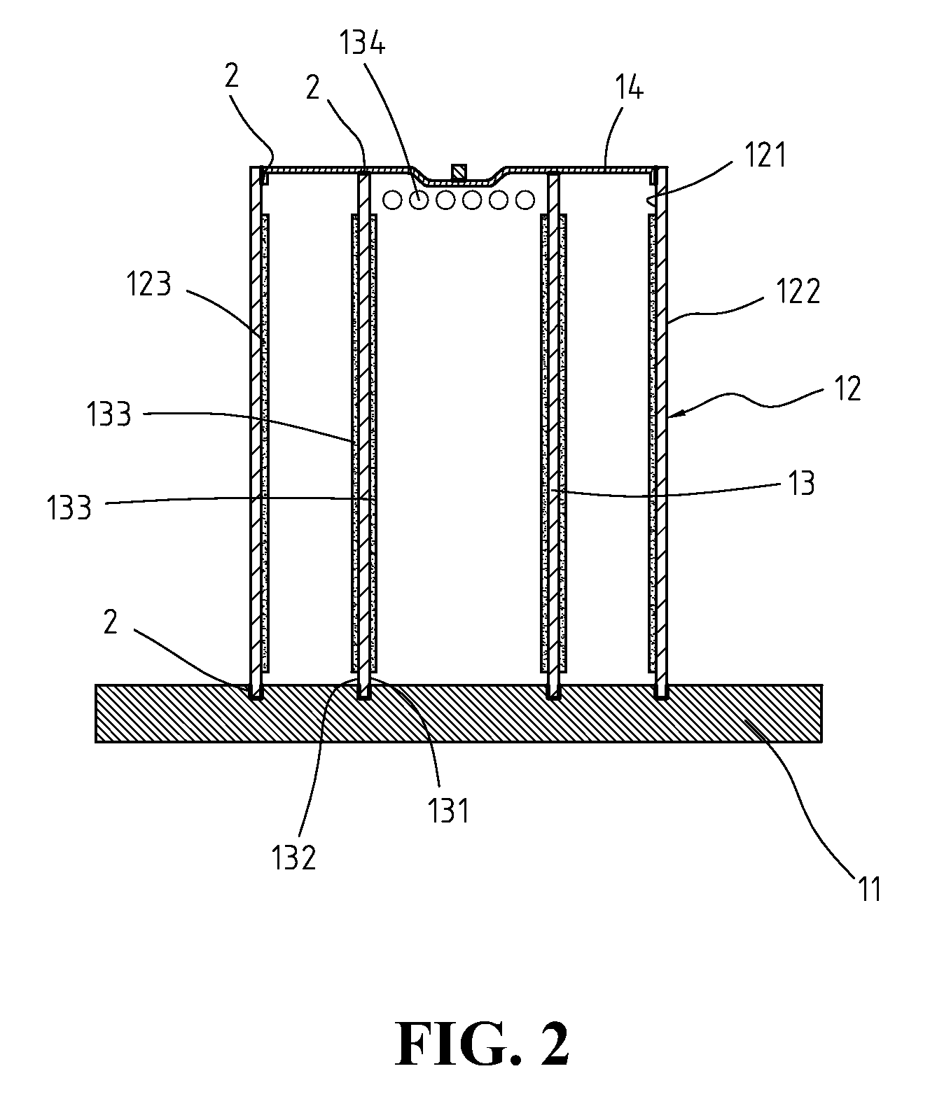
[0026]With further reference to FIG. 2, the base (11) is a plate of highly conductive metal and has a top surface and two concentric circular grooves. The concentric circular grooves are formed in the top surface and comprise an inner groove and an outer groove.

[0027]The core pipe (13) is cylindrical and a highly conductive metal, is copper-silver alloy brazed securely in the inner groove of the base (11) with a gas-tight fit, protrudes up from the base (11) and comprises an inner surface (131), an outer surface (132), an open top, multiple holes (134) and a wick (133). The holes (134) are formed around the core pipe (13) away from the base (11). The wick (133) is formed on the inner surface (131) and outer surface (132) between but not in contact ...


PUM


Abstract

A heat sink assembly in accordance with the present invention increases heat dissipation area, improves heat dissipation efficiency and comprises a base, a core pipe, an outer pipe, a top cover and a working fluid. The base has a top surface. The core pipe is mounted securely on and protrudes from the top surface with an air-tight fit and comprises an inner surface, an outer surface, a wick, multiple holes and a top. The wick is formed on the inner and outer surface. The outer pipe is mounted securely on and protrudes from the base concentrically around the core pipe and comprises an inner surface, an outer surface, a wick and a top. The wick is formed on the inner surface. The holes are formed around the core pipe away from the base. The top cover closes the top of the core pipe and the top of the outer pipe.

Description

FIELD OF THE INVENTION[0001]A heat sink assembly in accordance with the present invention is a heat pipe and particularly a heat pipe assembly having a core pipe and an outer pipe.BACKGROUND OF THE INVENTION[0002]Recently, performance of electronic equipment has increased dramatically with a commensurate reduction in equipment size. Higher performance has resulted in more internal heat and higher operating temperature. Without effective dissipation of the increased heat, reliability and life span of the associated electronic equipment will be adversely affected.[0003]To dissipate heat from electronic equipment, conventional heat sinks and fans are used. Conventional heat sinks use fins to increase the surface area so more heat can be transferred and dissipated. However, smaller electronic equipment size limits the number and size of fins that can be used to effectively dissipate heat generated by the electronic equipment. Therefore, using a heat pipe is necessary for heat dissipatio...

Claims


Application Information

Patent Timeline
IPC IPC(8): F28D15/00
CPCF28D15/046H01L23/427H01L2924/0002H01L2924/00
Inventor LIAO, WEN-CHIH
Owner LIAO WEN CHIH
Features
  • Generate Ideas
  • Intellectual Property
  • Life Sciences
  • Materials
  • Tech Scout
  • Unparalleled Data Quality
  • Higher Quality Content
  • 60% Fewer Hallucinations
Learn More