
Method of mounting conductive ball and conductive ball mounting apparatus

a technology of mounting apparatus and conductive ball, which is applied in the direction of soldering apparatus, manufacturing tools, non-printed masks, etc., can solve the problems of low manufacturing efficiency, difficult to move all the excess solder balls, and complicate maintenance, so as to achieve high reliability

Active Publication Date: 2009-03-19
SHINKO ELECTRIC IND CO LTD
View PDF4 Cites 14 Cited by
  • Summary
  • Abstract
  • Description
  • Claims
  • Application Information

AI Technical Summary

Benefits of technology

[0015]It is an object of the present invention to provide a method of mounting a conductive ball and a conductive ball mounting apparatus which are capable of mounting conductive balls with high reliability while efficiently removing excess conductive balls on a mask, in a method for mounting the conductive balls on a substrate through the mask.
[0020]In the present invention, unlike the prior arts, makes it possible collectively to remove the excess conductive balls by using the ball removal film without moving the brush repeatedly until no excess conductive balls remain on the mask. Accordingly, the manufacturing efficiency can be remarkably improved. Moreover, unlike a method in which the conductive balls are moved by blowing air, no conductive balls can fly to the outside since the conductive balls are bonded to the adhesive film and are then removed.
[0021]In addition, since no excess conductive balls remain around the opening portions of the mask, this method prevents the excess conductive balls from being mounted on the substrate through the opening portions of the mask when the mask is moved upward to be removed from the substrate. Accordingly, a single conductive ball can be mounted on each of the connection pads of the substrate with high reliability.
[0024]As described above, in the present invention, conductive balls can be mounted on a substrate with high reliability while excess conductive balls on the mask are removed efficiently.

Problems solved by technology

Consequently, a long time is required for the operation, and, hence, the manufacturing efficiency is low.
Furthermore, solder balls sometimes adhere to the brush, which is likely to complicate the maintenance.
By contrast, when the wind pressure is set low enough to prevent solder balls from flying to the outside, it is extremely difficult to move all the excess solder balls.

Method used


Image

  • Method of mounting conductive ball and conductive ball mounting apparatus
  • Method of mounting conductive ball and conductive ball mounting apparatus
  • Method of mounting conductive ball and conductive ball mounting apparatus

Examples


first embodiment

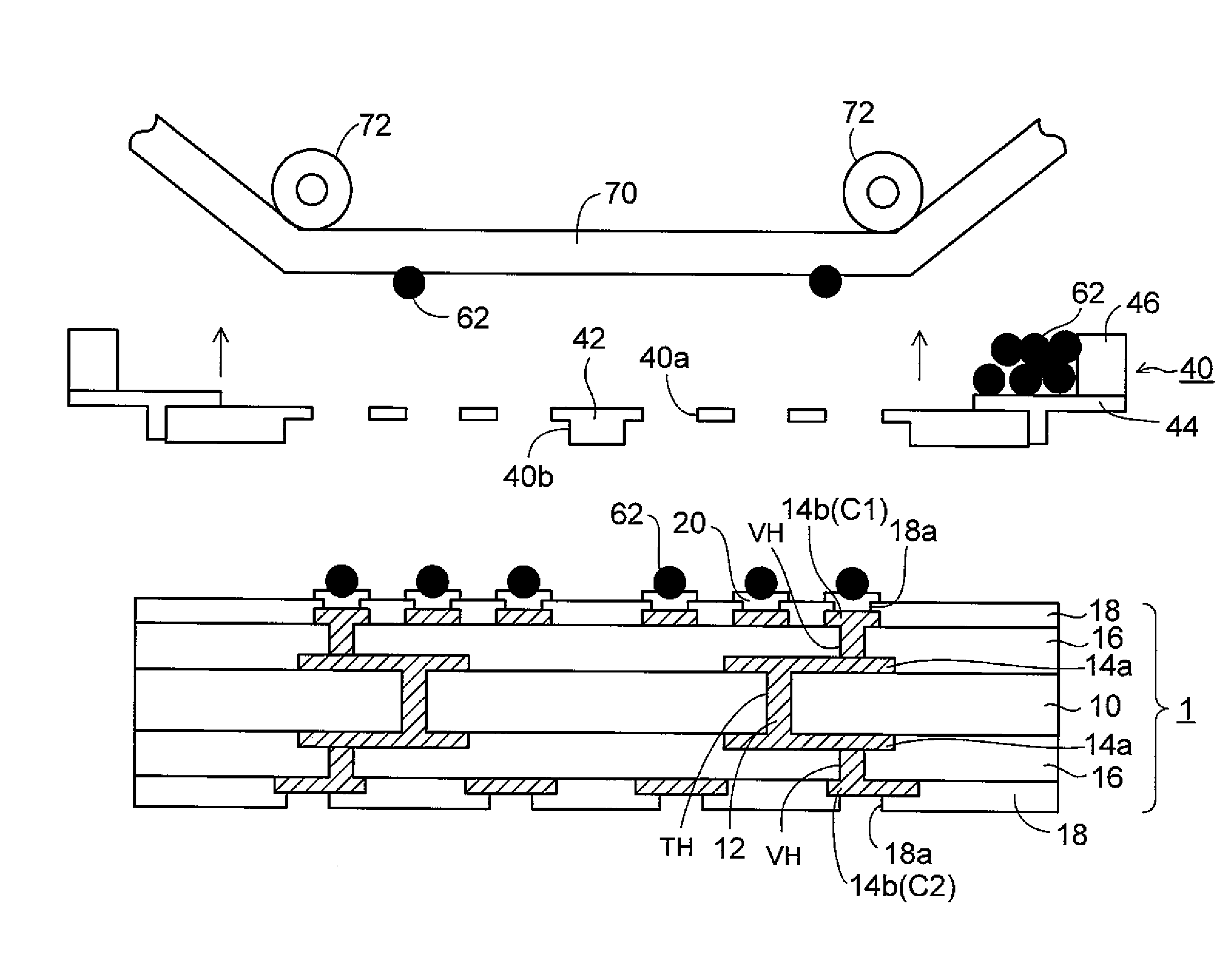
[0042]FIGS. 3 to 9 are cross-sectional views showing a method of mounting a conductive ball, according to a first embodiment of the present invention; FIGS. 10 to 12 are cross-sectional views showing a method of mounting a semiconductor chip on a wiring substrate on which conductive balls are mounted; and FIG. 13 is a cross-sectional view showing a conductive ball mounting apparatus similarly.

[0043]In the method of mounting a conductive ball, according to the first embodiment, firstly, as shown in FIG. 3, a wiring substrate 1 on which conductive balls are to be mounted is prepared. In the wiring substrate 1, through holes TH are formed in a core substrate 10 made of glass epoxy resin or the like, and the through holes TH are filled respectively with through-hole electrodes 12 made of copper or the like. In addition, first wiring layers 14a connected to each other via through-hole electrode 12 and made of copper, are respectively formed on both surfaces of the core substrate 10.

[0044...

second embodiment

[0084]FIGS. 14 and 15 are cross-sectional views showing a method of mounting a conductive ball according to a second embodiment of the present invention. In the second embodiment, the same elements as those in the first embodiment are denoted by the same reference numerals, and the detailed description of those elements are omitted.

[0085]In the above-described method of mounting a conductive ball according to the first embodiment, by directly disposing the adhesive film 70 on the mask 40 which is flat while controlling the height position, the excess conductive balls 62 on the mask 40 are removed to be bonded to the adhesive film 70

[0086]By this matter, in the case where the adhesive film 70 is displaced toward the mask 40 and is consequently placed in contact with the mask 40, it is assumed that not only the excess conductive balls 62 on the mask 40 but also the conductive balls 62 transferred into the opening portions 40 of the mask 40 are removed to be bonded to the adhesive film...


PUM

PropertyMeasurementUnit
Electrical conductoraaaaaaaaaa
Heightaaaaaaaaaa
Adsorption entropyaaaaaaaaaa

Abstract

A method of mounting a conductive ball according to the present invention includes the steps of, disposing a mask on a substrate including connection pads, the mask having opening portions corresponding to the connection pad, supplying conductive balls on the mask, arranging the conductive balls on the connection pad of the substrate through the opening portions of the mask by moving the conductive balls to one end side of the mask by ball moving member (a brush), and removing excess conductive balls remaining on a region of the mask where the opening portions are provided, by bonding the excess conductive balls to a ball removal film (adhesive film).

Description

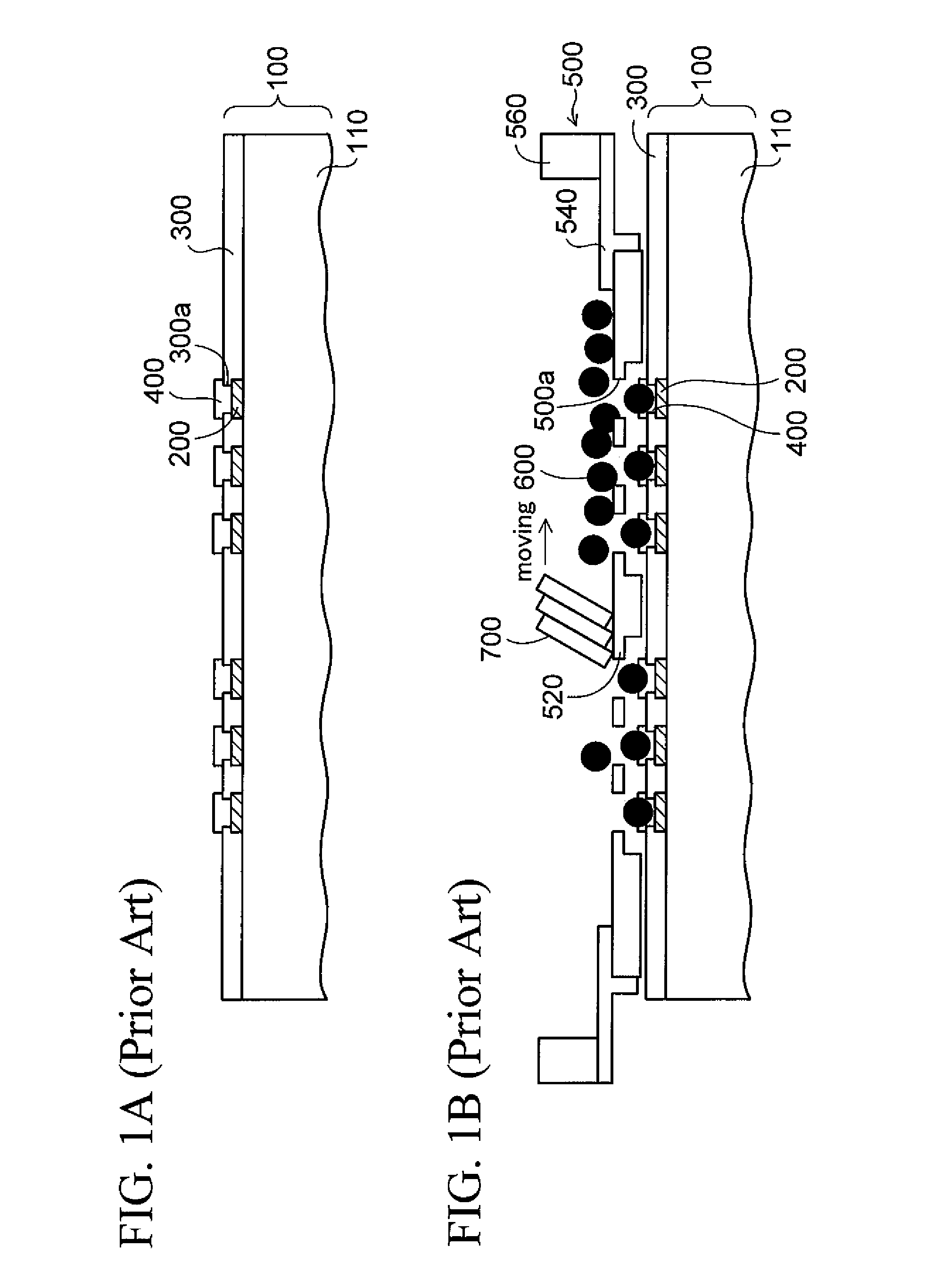
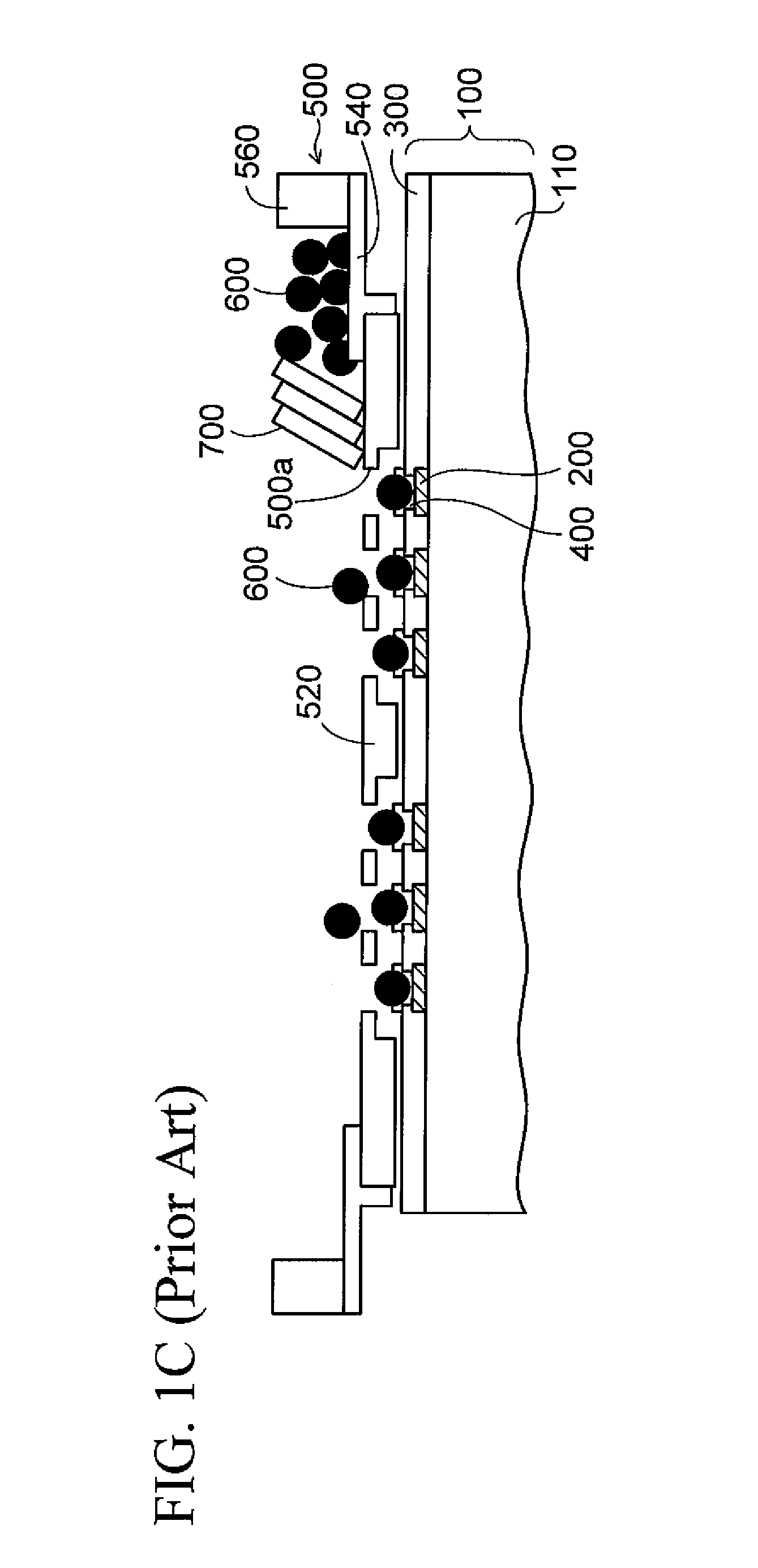
CROSS-REFERENCE TO RELATED APPLICATIONS[0001]This application is based on and claims priority of Japanese Patent Application No. 2007-239045 filed on Sep. 14, 2007, the entire contents of which are incorporated herein by reference.BACKGROUND OF THE INVENTION[0002]1. Field of the Invention[0003]The present invention relates to a method of mounting a conductive ball and a conductive ball mounting apparatus, more particularly, a method of mounting a conductive ball and a conductive ball mounting apparatus, for mounting a conductive ball on a wiring substrate or the like to form a bump electrode.[0004]2. Description of the Related Art[0005]In the prior art, there has been a method of forming a solder ball on a connection pad of a wiring substrate on which a semiconductor chip or the like is to be mounted, and thereby forming a bump electrode. In such a method of mounting a solder ball, firstly, as shown in FIG. 1A, a wiring substrate 100 on which solder balls are to be mounted is prepar...

Claims


Application Information

Patent Timeline
IPC IPC(8): B23K31/00
CPCB23K3/0623H01L2924/01029H01L21/4853H01L2224/16225H05K3/3478H05K2203/0139H05K2203/0191H05K2203/041H05K2203/0557H01L2224/11005H01L24/742H01L2224/11003H01L2224/11334H01L2924/01005H01L2924/01006B23K2201/40B23K2101/40
Inventor SAKAGUCHI, HIDEAKIIIDA, KIYOAKI
Owner SHINKO ELECTRIC IND CO LTD
Learn More