Liquid droplet ejecting apparatus and liquid droplet ejecting method
- Summary
- Abstract
- Description
- Claims
- Application Information
AI Technical Summary
Benefits of technology
Problems solved by technology
Method used
Image
Examples
working example
[0098]The effects of the present invention will be illustrated based on a working example.
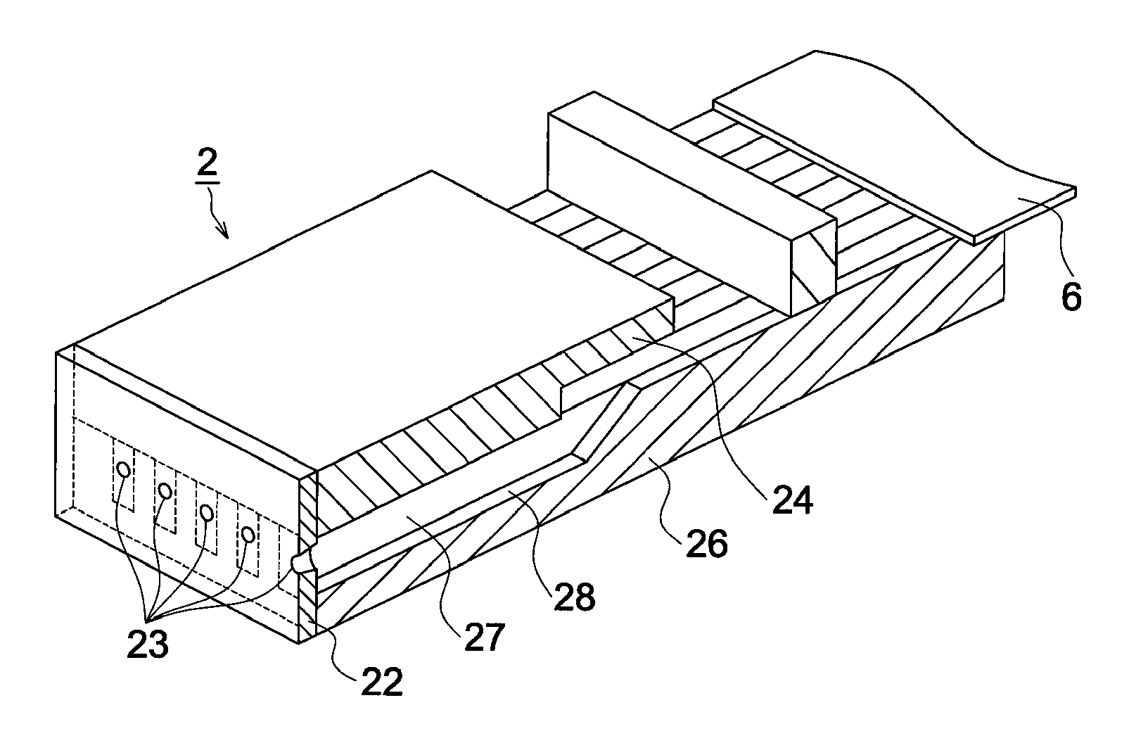
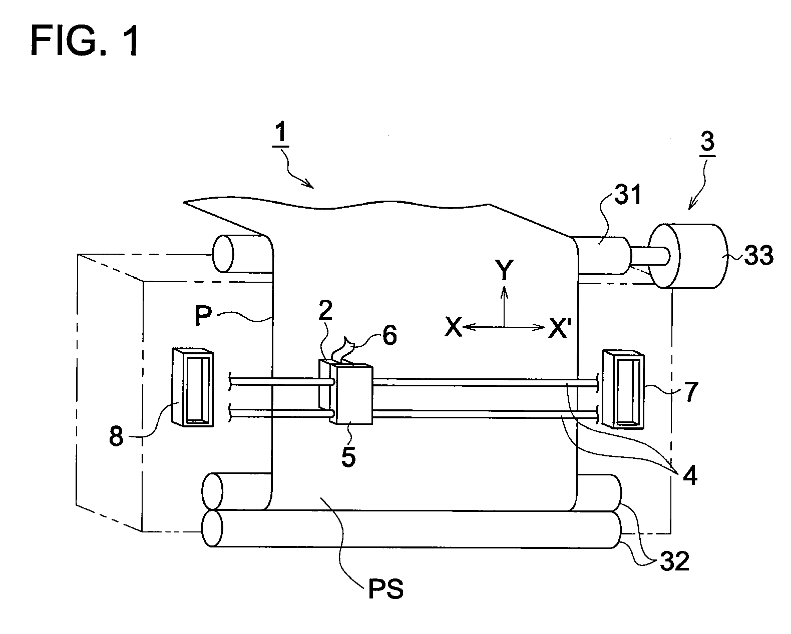
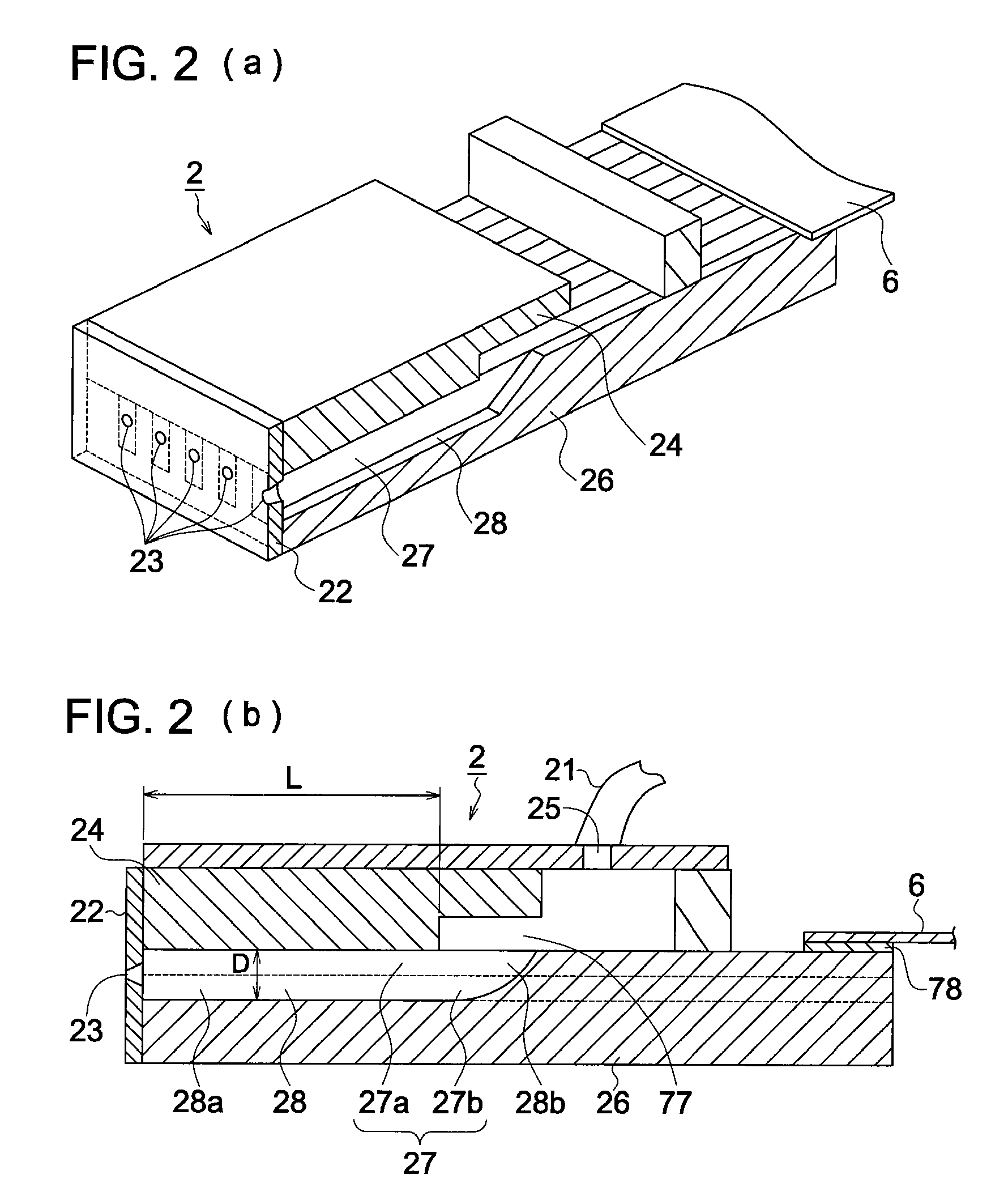
[0099]First, a recording head was prepared under the following conditions. As shown in FIGS. 1-3, multiple grooves were formed in a base plate made of PZT to form the side walls and aluminum vapor deposited electrodes were formed on the side surfaces of each side wall. The recording head was formed by bonding a cover plate to the upper surface of each side wall using an adhesive and bonding it to the front end, a nozzle forming member (thickness 75 μm) into which a nozzle with a diameter of φ20 μm and a taper angle of 6.3° is formed. The nozzle has a circular truncated cone shape and the taper angle of the nozzle is defined as ½ of the circular cone shape. And the length of the nozzle is equal to the thickness of the nozzle forming member.
[0100]The density of the pressure chambers was set at 180 dpi (141 μm pitch); the width W of each pressure chamber was 85 μm, the length L 5 mm, and the depth...
PUM
 Abstract
Description
Claims
Application Information
 - R&D
- Intellectual Property
- Life Sciences
- Materials
- Tech Scout
- Unparalleled Data Quality
- Higher Quality Content
- 60% Fewer Hallucinations
Browse by: Latest US Patents, China's latest patents, Technical Efficacy Thesaurus, Application Domain, Technology Topic, Popular Technical Reports.
© 2025 PatSnap. All rights reserved.Legal|Privacy policy|Modern Slavery Act Transparency Statement|Sitemap|About US| Contact US: help@patsnap.com


