Optical measurement device for trace liquid sample

Active Publication Date: 2009-03-19
SHIMADZU CORP
View PDF2 Cites 10 Cited by
  • Summary
  • Abstract
  • Description
  • Claims
  • Application Information

AI Technical Summary

Benefits of technology

[0017]In the optical 
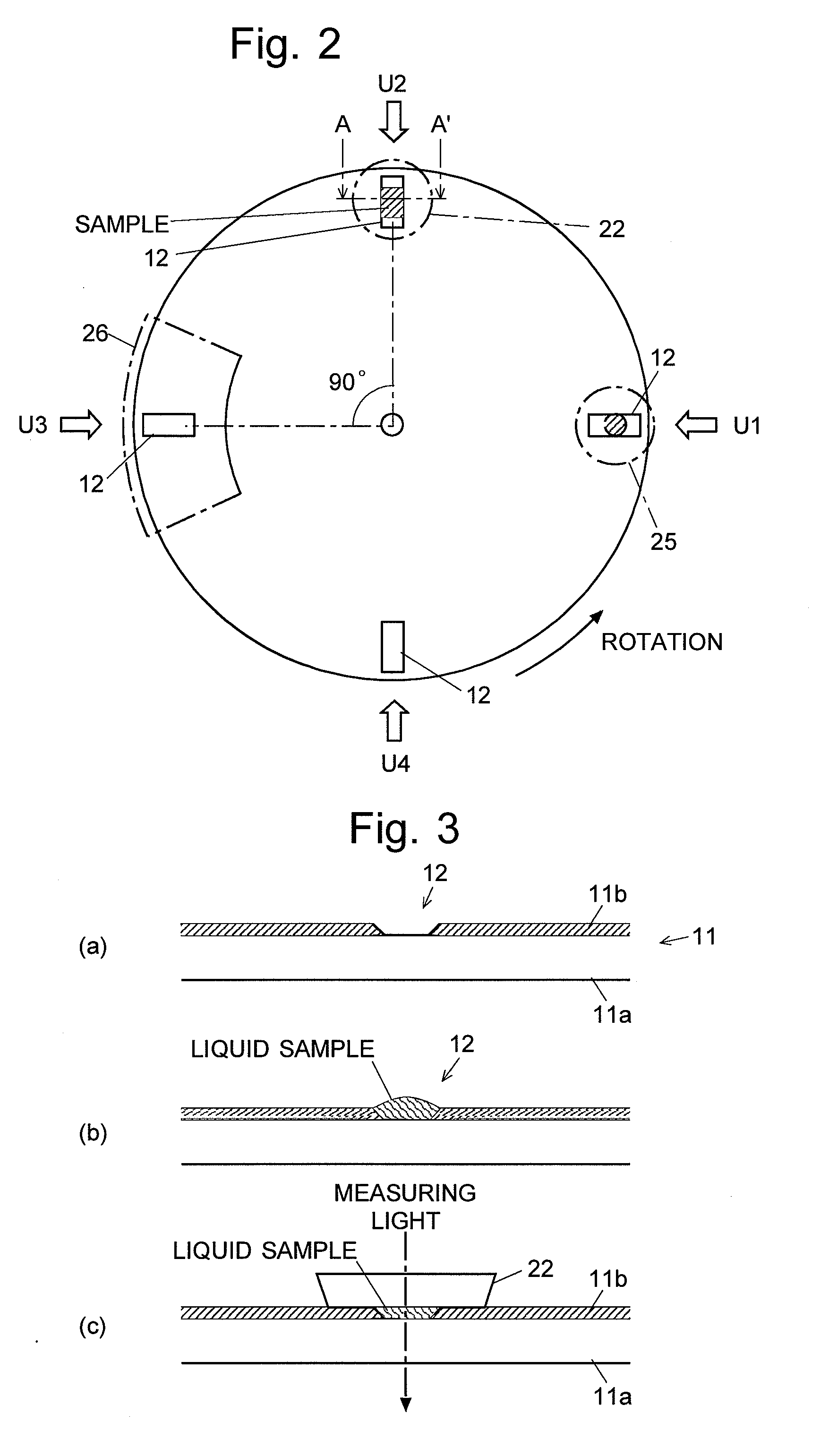
measurement device according to the present invention, when one of the plurality of sample holders is located at the sample supply position, the sample supply section drops a trace amount of a liquid sample into the sample holder. The dropped liquid sample forms a swelling liquid drop due to surface tension, for example, in the groove or on the upper surface of the protrusion. Thereafter, when the moving mechanism moves the supporting plate so that the sample holder comes to the measuring position, the suppressing plate is moved to cover the 
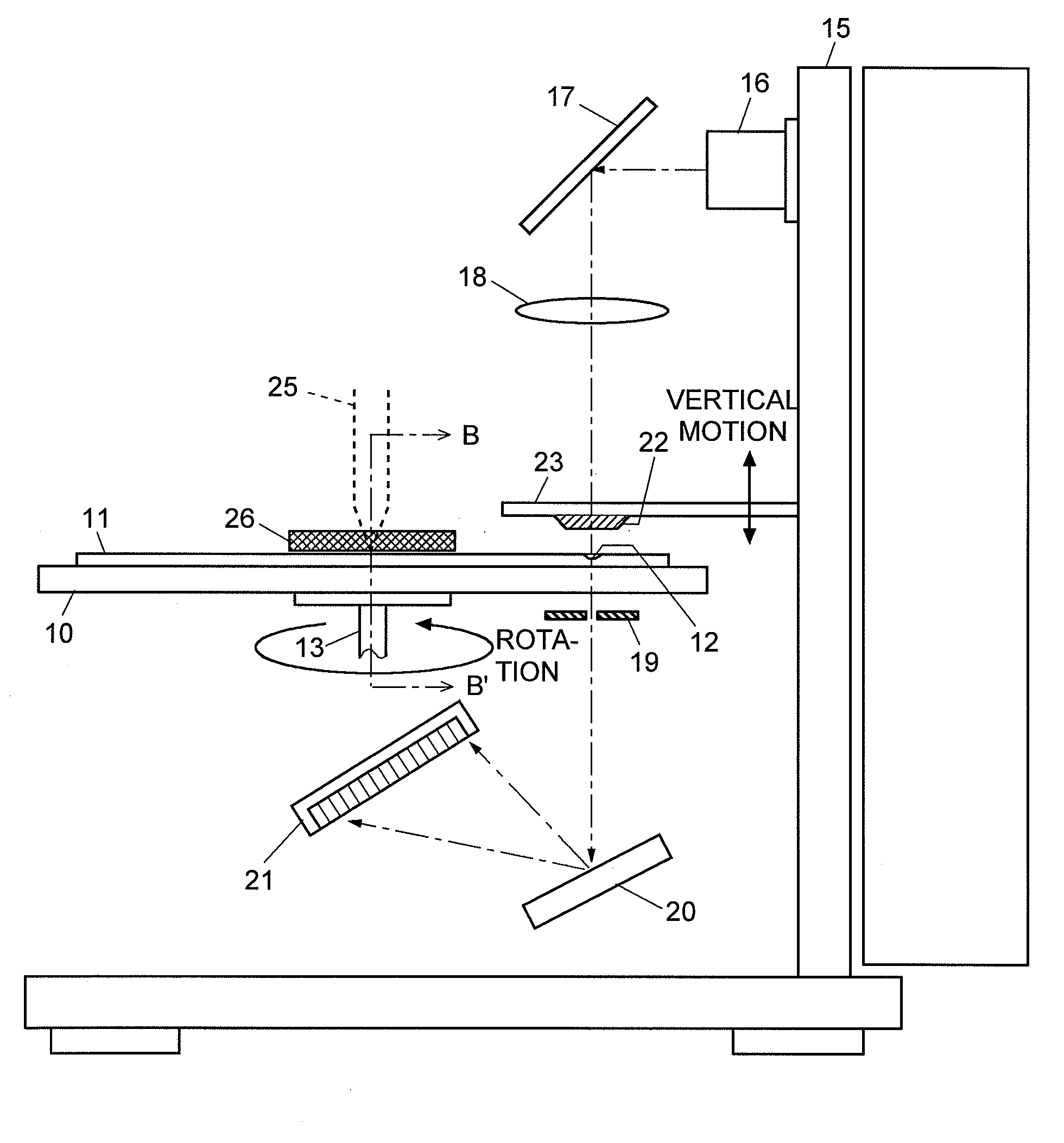
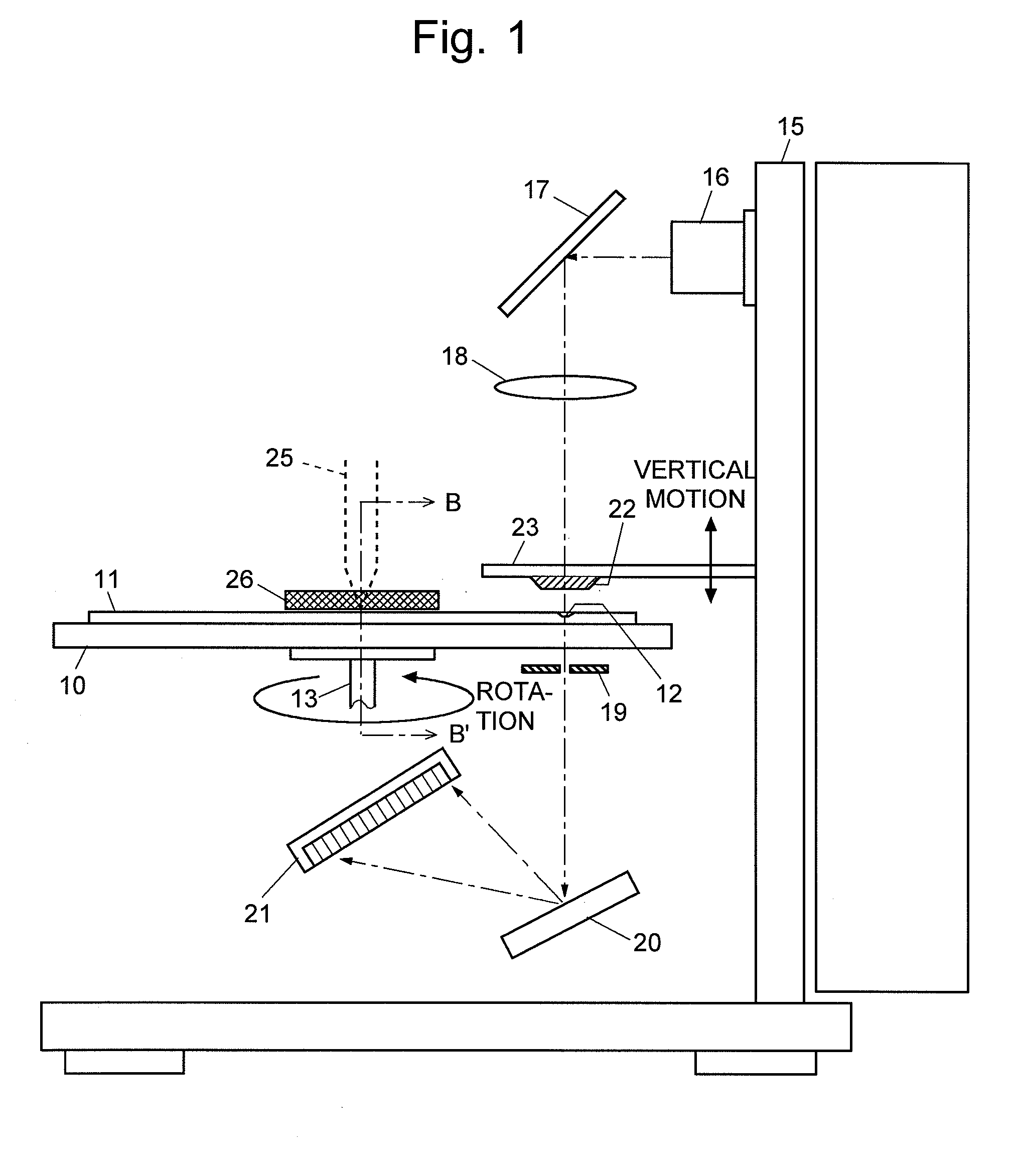
liquid drop held in the sample holder, with the result that the liquid sample is filled in the space between the lower surface of the suppressing plate and the bottom surface of the sample holder. In this state, the light measuring section irradiates the liquid sample with a measuring light and then measures the transmitted light. The distance from an upper surface corresponding to the interface between the liquid sample and the suppressing plate to a bottom surface corresponding to the interface between the liquid sample and the sample holder is determined to be the optical path length in the liquid sample.
[0018]When the measurement is completed, the moving mechanism moves the supporting plate so that the sample holder moves from the measuring position to the sample supply position. On the path of movement, a first wiping mechanism is installed. The sample holder contacts the first wiping mechanism, or the sample holder slides while keeping contact with the first wiping mechanism, thereby the liquid sample held by the sample holder is wiped off by the first wiping mechanism. Thereafter, the sample holder returns to the sample supply position in a state where a liquid sample as a next measurement object can be dropped into the sample holder. On the other hand, when the measurement by the light measuring section is completed, the second wiping mechanism wipes off the residue of the liquid sample attached to the lower surface of the suppressing plate so as to prepare for the next measurement.
[0019]The above operation is sequentially and repeatedly performed on each of the plurality of the sample holders, and at the same time different operations simultaneously progress in such a manner that, for example, when the measurement is performed on a first sample holder, a liquid sample is dropped into a second sample holder, and further the first wiping mechanism wipes off a measured liquid sample in a third sample holder.
[0020]As previously mentioned, according to the optical measurement device for a trace liquid sample of the present invention, the operation of removing the unnecessary measured liquid sample is automatically performed in conjunction with the switching of the positions of the sample holders along with the movement of the supporting plate. Therefore, an operator does not need to do some troublesome tasks such as the wiping of a sample, and thereby labor savings can be achieved. On the other hand, since each of a series of operations from the supply (dropping) through the measurement to the removal of a liquid sample is automatically and cyclically performed, it is possible to improve measurement throughput and thus it is possible to treat a large amount of samples in a relatively short period of time.
[0021]Moreover, one of the embodiments of the present invention may have a configuration in which the moving mechanism drives the supporting plate to rotate around a vertical axis, and the plurality of sample holders are disposed on a circle centering the vertical axis. In this configuration, one of the sample holders is moved from the measuring position to the sample supply position as the supporting plate rotates in one direction, and the first wiping mechanism is disposed on the path of movement.
[0022]This configuration can be easily achieved by properly disposing the light measuring section, the sample supply section, and the first wiping mechanism around the axis of rotation as a center, and further a conventional motor can be used as the moving mechanism that drives the supporting plate to rotate in one direction. Due to this simple structure, the cost can be reduced.

Problems solved by technology

However, in many cases, the amount of a liquid sample to be analyzed is extremely small.
Especially, since samples are precious and expensive in a DNA-related analysis, it is sometimes necessary to analyze a liquid sample in an amount of less than several microliters.
Therefore, the aforementioned cuvette cell cannot be used for the analysis of a trace liquid sample.
This operation is a troublesome task, because it needs to be performed manually every time analysis of one sample is finished.
Moreover, there is a problem of low throughput, since it is not possible to measure a plurality of samples while automatically changing the samples.

Method used


Image

  • Optical measurement device for trace liquid sample
  • Optical measurement device for trace liquid sample
  • Optical measurement device for trace liquid sample

Examples


Embodiment Construction

[0034]The following description will discuss an ultraviolet-visible spectrophotometer as one embodiment of the optical measurement device for trace liquid sample according to the present invention. FIG. 1 is a side view illustrating a schematic structure of the ultraviolet-visible spectrophotometer according to the present embodiment.

[0035]In FIG. 1, a disk-like sample plate 11 (corresponding to the supporting member of the present invention) having thereon four sample holders 12 for holding the liquid sample is loaded onto a disk-like sample table 10 which extends in a substantially horizontal plane. The sample plate 11 integrated with the sample table 10 can be rotated by a driving mechanism (corresponding to the moving mechanism of the present invention) including a motor or other members, not shown in FIG. 1, around a rotation axis 13 as the center within a substantially horizontal plane. The sample table 10 has an opening beneath each of the four sample holders 12.

[0036]Light i...


PUM


Abstract

In a spectrophotometer for measuring transmitted light of a trace liquid sample, four sample holders 12 are provided on a disk-like sample plate 11 while spaced apart by 90 degrees. The sample plate 11 is driven to rotate so that each of the sample holders 12 is sequentially moved to a sample supply position U1, a measuring position U2, a wiping position U3 and a waiting position U4. At the sample supply position U1, a trace amount of the liquid sample is dropped into a groove of the sample holder 12. Then at the measuring position U2, a window plate 22 is lowered onto the groove so as to determine the optical path length. Next, measurement of the transmitted light is performed. Further, while the sample holder 12 moves from the measuring position U2 to the waiting position U4, the liquid sample is absorbed and removed by contact with a cleaning pad 26. The liquid sample attached to the window plate 22 is wiped out by another pad. Since the operation to wipe off the measured sample is automatically performed, it is possible to improve the throughput of the measurement.

Description

TECHNICAL FIELD[0001]The present invention relates to an optical measurement device for measuring a liquid sample by irradiating the liquid sample with light and measuring the transmitted light. The present invention especially relates to an optical measurement device, such as a spectrophotometer, for measuring the transmission characteristics of a trace liquid sample.BACKGROUND ART[0002]When a liquid sample is analyzed to measure the transmission characteristics such as transmittance and absorbency, by a spectrophotometer such as an ultraviolet-visible spectrophotometer, a prism or cylindrical-shaped cuvette for holding the liquid sample is normally used. An inner volume of a cuvette is normally several milliliters or more, and thus it is necessary to prepare a liquid sample in a sufficient amount to fill the cuvette.[0003]Recently, an ultraviolet-visible spectrophotometer has been often used for determining protein or DNA quantity in the field of biochemistry. However, in many cas...

Claims


Application Information

Patent Timeline
IPC IPC(8): G01J3/42
CPCG01N21/253G01N35/025G01N2021/135G01N2021/0353G01N2021/115G01N2021/035
Inventor TSUKUDA, YASUO
Owner SHIMADZU CORP
Why Eureka
Try Eureka