Disk device

a technology of a disk and a locking mechanism, which is applied in the direction of electrical apparatus construction details, instruments, and casings/cabinets/drawers, etc., can solve the problems of instability in the writing and reading operations of the hdd, shake the hdd holding case, etc., and achieve the effect of facilitating insertion and removal from the bracket, and effectively inhibiting sympathetic vibration

Inactive Publication Date: 2009-03-19
AISIN AW CO LTD
View PDF14 Cites 50 Cited by
  • Summary
  • Abstract
  • Description
  • Claims
  • Application Information

AI Technical Summary

Benefits of technology

[0017]The above-described spring members that face the first side panel, the spring members that face the second side panel, and the spring members of the second group that face the planar top or bottom panel may press against the other of the bracket and the case at a position where a plane that is orthogonal to the direction of the relative movement intersects the other of the bracket and the case. In this configuration, the spring members of the first group and the second group exert spring forces against the other of the bracket and the case at the same position in the direction of the relative movement. This makes it possible to effectively inhibit sympathetic vibration in the sheet metal from which the case is fabricated.
[0018]The disk unit may be fastened to the case at a plurality of points in a straight line that is orthogonal to the direction of the relative movement and that lies within the above-mentioned plane that is orthogonal to the direction of the relative movement. In this configuration, the spring members of the first group and the second group exert spring forces against the other of the bracket and the case at the points where the disk unit is fastened to the case. This makes it possible to effectively inhibit sympathetic vibration in the case, which is combined into a single unit with the disk unit.
[0019]In one embodiment, the guide member is on the bracket, supports the case from below and guides the relative movement. In such an embodiment, the planar surface, described above as orthogonal to the side panel of the case, may be folded rails that extend inwardly from the side panels and longitudin...

Problems solved by technology

Therefore, the HDD holding case is shaken by the vibration of the bracket that results from the vibration of the vehicle.
Sympathetic vibration, in ...

Method used


Image

  • Disk device
  • Disk device
  • Disk device

Examples


embodiment 1

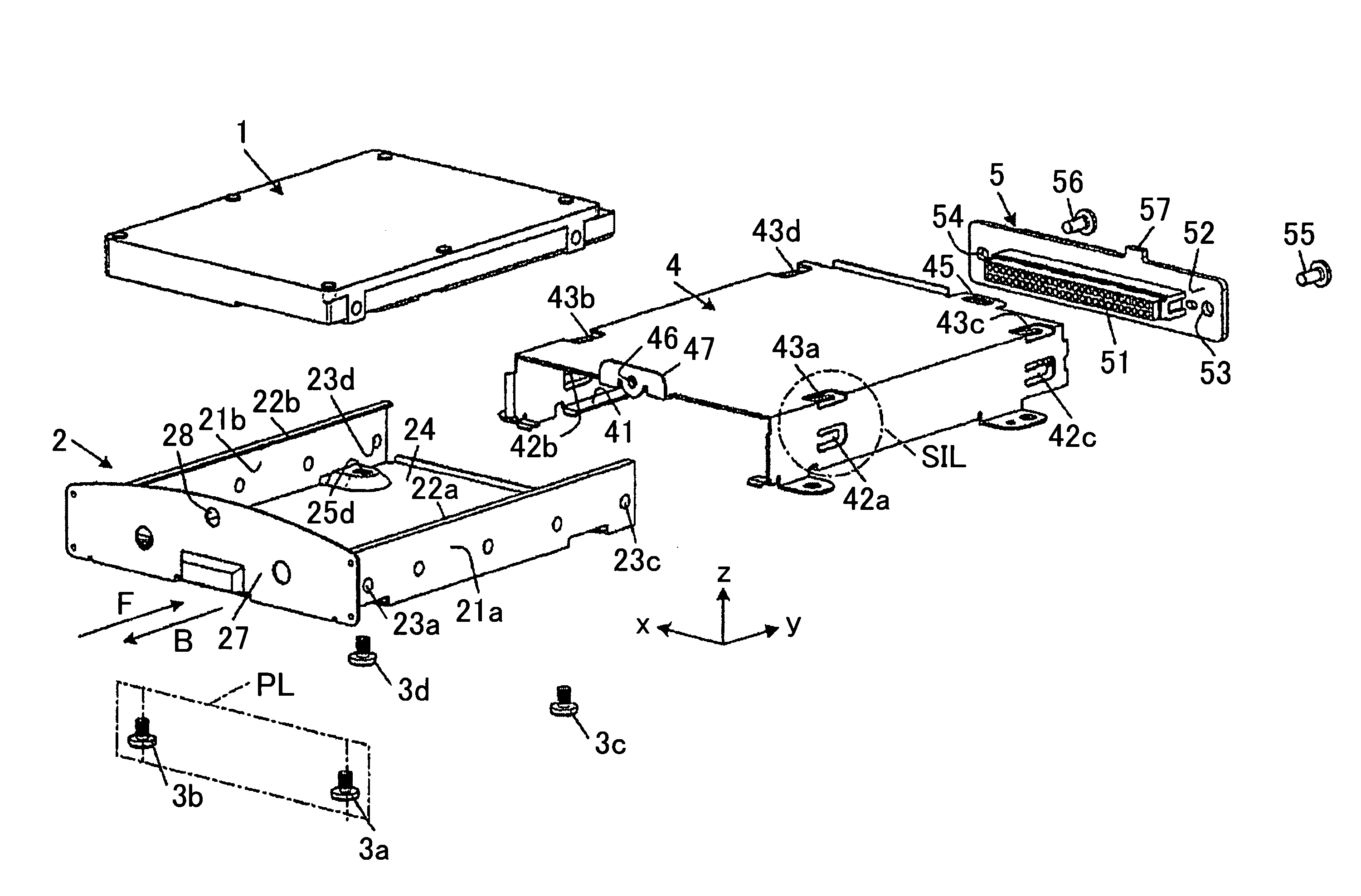
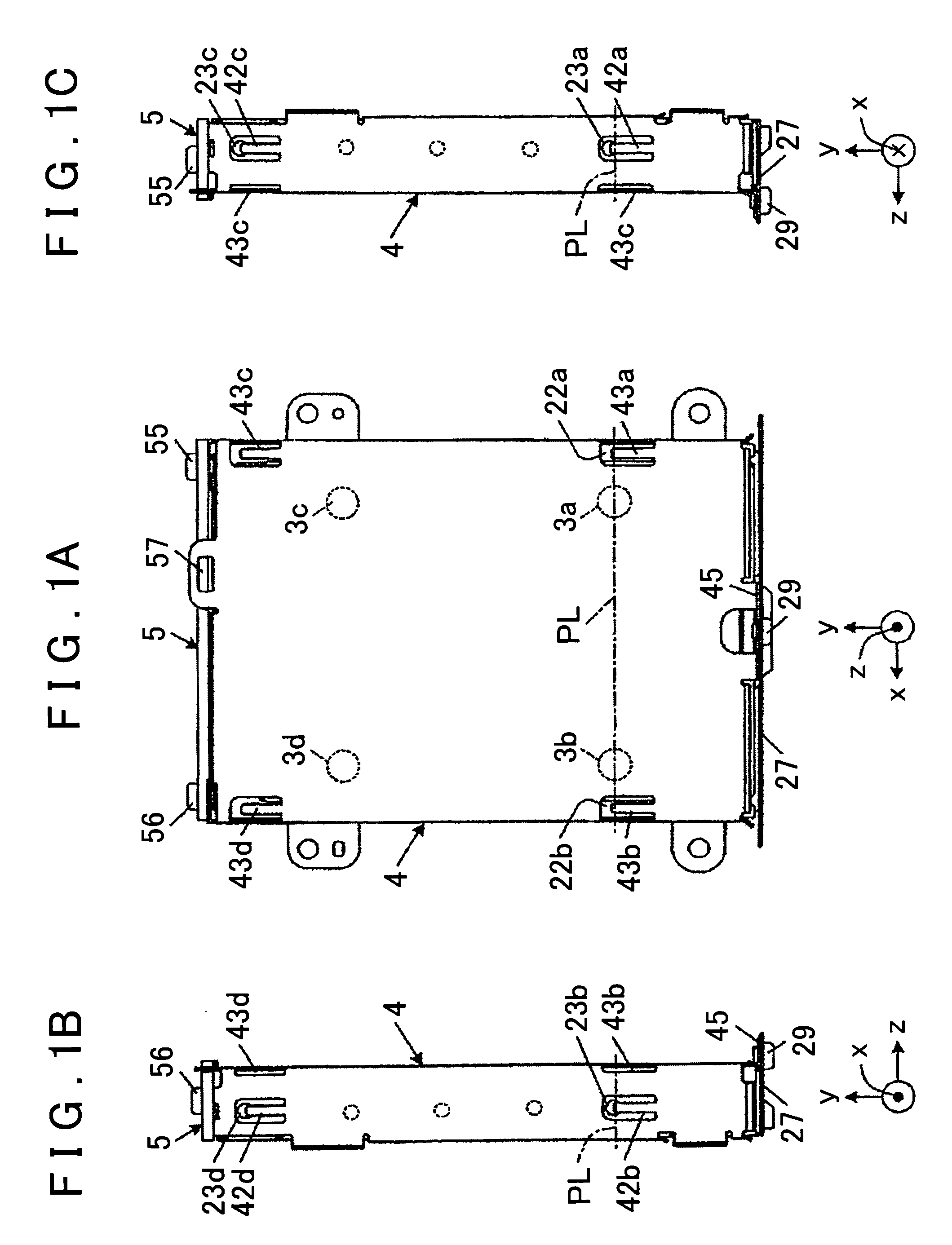
[0031]FIGS. 1A-1C show a hard disk drive (HDD) device as one embodiment of the present invention. The HDD device is installed in a vehicle and provides map information, road information, and the like to a navigation system.

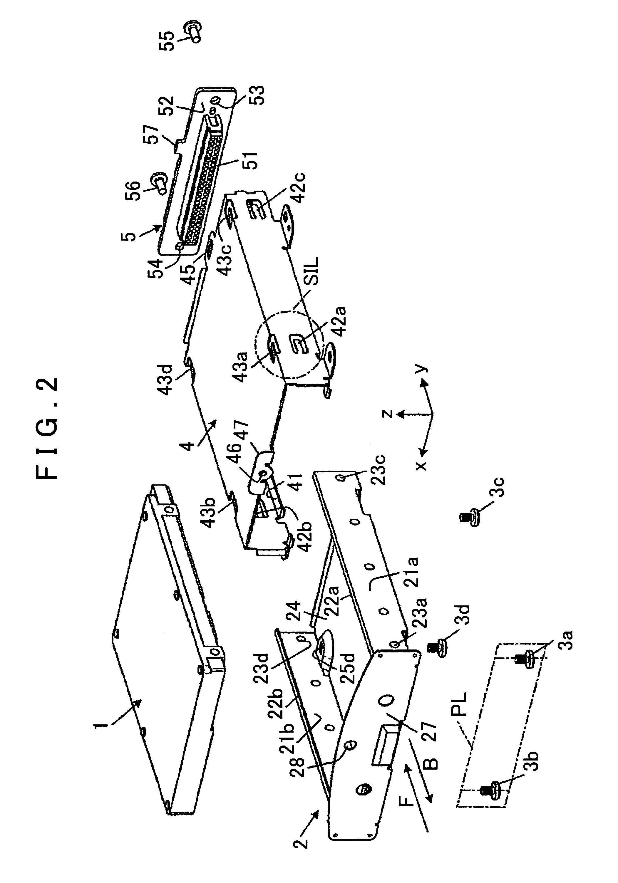
[0032]An HDD unit 1 shown in FIG. 2 is a disk unit which contains a hard disk, a drive motor, a read-write head, a head actuator, and a control circuit board, as in a conventional HDD unit. A male connector (not shown in the drawings) includes a plurality of connector pins which extend in a case insertion direction F (FIG. 2) toward the rear edge of the control circuit board. When the male connector is pushed into the case in direction F, the male connector connects to a female connector 51 in a printed wiring panel 5 that is mounted on the bracket 4. A metal bottom plate (not shown in the drawings), that is electrically connected to grounding conductor of the control circuit board, is provided on the bottom face of the HDD unit 1. Four female threaded holes are p...


PUM


Abstract

A disk device includes a disk unit housing a disk-shaped storage medium, a case holding the disk unit, a bracket holding the case, and a guide member guiding sliding movement of the case in and out from the bracket. The disk device also includes spring members on one of the bracket and the case, distributed in the direction of the relative movement. Each of the spring members extends longitudinally in the direction of the movement. Distal ends of the spring members face and press against the other of the bracket and the case. Base portions of the spring members are integral with the one of the bracket and the case. The spring members inhibit lateral vibration of the case by pressing against small projections on the case. Other spring members inhibit vertical vibration of the case by pressing against sliding support rails of the case. A face plate of the case absorbs vibration in the longitudinal direction.

Description

INCORPORATION BY REFERENCE[0001]The disclosure of Japanese Patent Application No. 2007-233996 filed on Sep. 10, 2007, including the specification, drawings and abstract is incorporated herein by reference in its entirety.BACKGROUND OF THE INVENTION[0002]1. Field of the Invention[0003]The present invention relates to a disk device that incorporates an information storage medium and, more particularly, relates to a structure that prevents or minimizes vibration of a disk unit housed therein.[0004]2. Description of the Related Art[0005]Japanese Patent Application Publication No. JP-A-2005-135564 discloses a disk unit that is inserted into a receiving slot of an electronic device. The disk unit includes a hard disk, a drive motor, a read / write head, and a head actuator. The disk unit is inserted into a bottom cover of the electronic device. A control circuit board is mounted on top of the disk unit, and a top cover is placed over the disk unit and joined to the bottom cover. Windows are...

Claims


Application Information

Patent Timeline
IPC IPC(8): H05K5/00
CPCG11B33/124
Inventor IKEDA, SHOUJITAKEI, EIICHIMORIMOTO, RYOUSUKE
Owner AISIN AW CO LTD
Why Eureka
Try Eureka