Wind turbine blades with trailing edge serrations

a technology of wind turbine blades and serrations, which is applied in the direction of liquid fuel engines, vessel construction, marine propulsion, etc., can solve the problems of wind turbine noise still a major obstacle to implementation, new, low-noise airfoil designs could only be applied at the outer portion of the blade span, and aero-elastic, structural, and load issues had to be carefully considered

Inactive Publication Date: 2009-03-19
GENERAL ELECTRIC CO
View PDF8 Cites 133 Cited by
  • Summary
  • Abstract
  • Description
  • Claims
  • Application Information

AI Technical Summary

Problems solved by technology

Although wind energy is one of the fastest growing sources of renewable energy, wind turbine noise is still a major obstacle to implementation.
For large, modern wind turbines, aerodynamic noise is considered to be the dominant source of this noise problem, and, in particular, so-called “trailing edge noise” caused by the interaction of turbulence in the boundary layer with the trailing edge of the blade.
A second challenge for

Method used


Image

  • Wind turbine blades with trailing edge serrations
  • Wind turbine blades with trailing edge serrations
  • Wind turbine blades with trailing edge serrations

Examples


Embodiment Construction

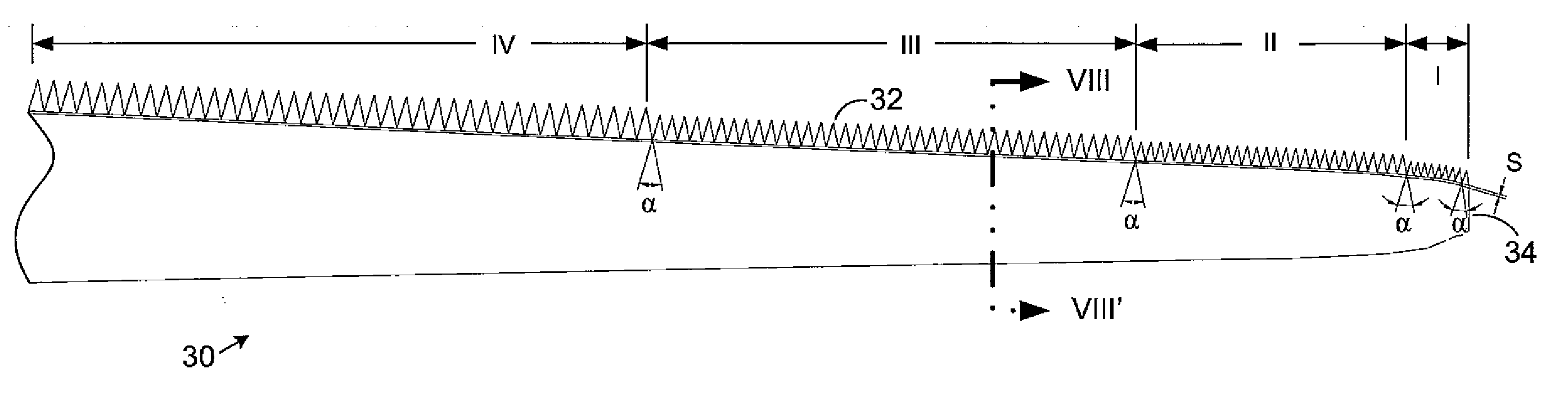
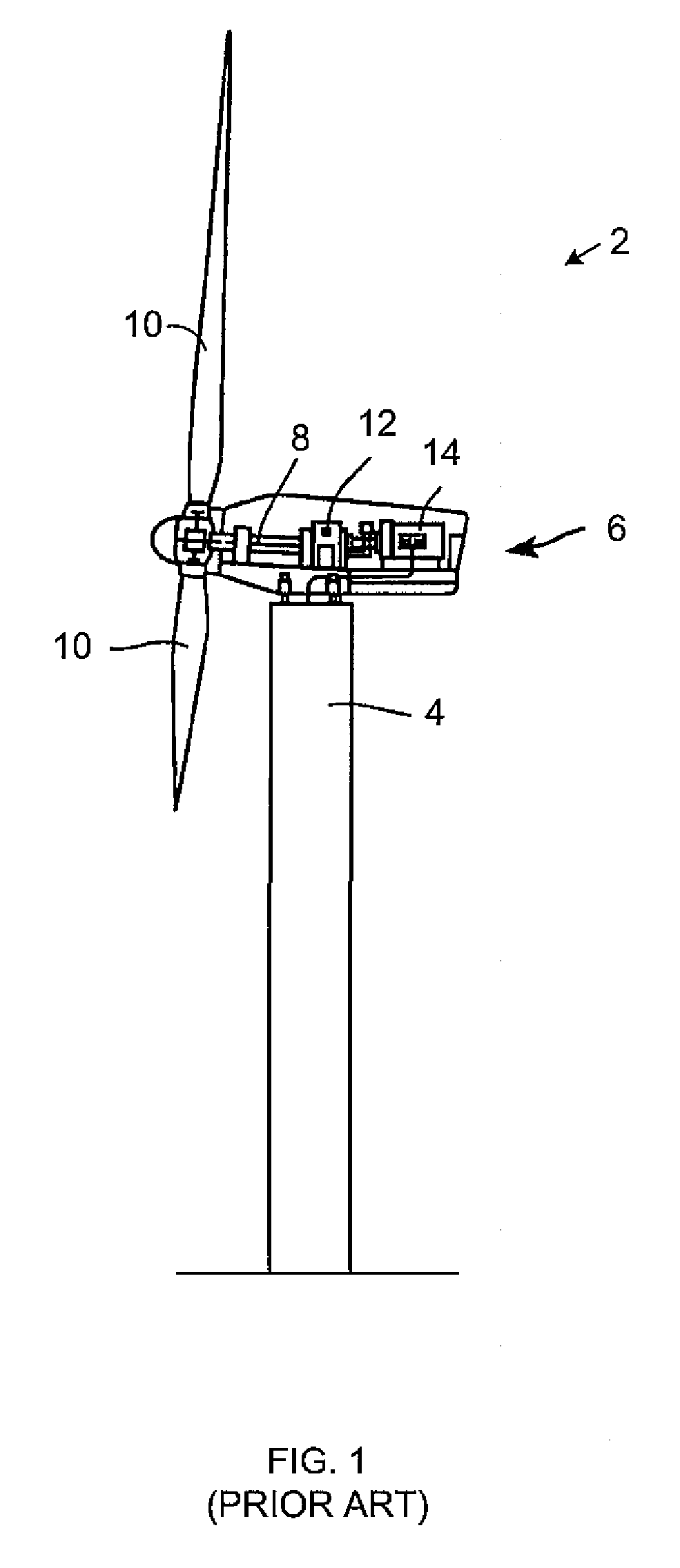
[0026]FIG. 6 is a schematic, plan view of one embodiment of a wind turbine blade 30 for use with the wind generator 2 shown in FIG. 1, or any other wind turbine. The blade 30 includes a serrated trailing edge 32 extending inboard from substantially near the tip 34 of the blade. For the examples illustrated here, the serrated trailing edge 32 is divided into four adjacent serrated sections identified by Roman numerals I through IV. However, any other number of sections may be provided, and the various sections may be spaced-apart by portions of the trailing edge without serrations and / or with other serrations.

[0027]Each section of the serrated trailing edge 32 may be formed separately or contiguously from any material, including aluminum, plastic, reinforced plastic, fiber reinforced plastic, glass fiber reinforced plastic, and / or other materials. For example, the serrated trailing edge 32 may be formed as one or more relatively stiff plates that do not significantly deform under the...


PUM


Abstract

A wind generator and turbine blade includes a trailing edge having several serrations, a length of the serrations in each of a plurality of sections of the trailing edge is between approximately 10% and 40% of a mean chord for the corresponding section; and a length to width ratio of each of the serrations is between approximately 1:1 to 4:1.

Description

BACKGROUND OF THE INVENTION[0001]1. Technical Field[0002]The subject matter described here generally relates to fluid reaction surfaces with specific blade structures, and, more particularly, to wind turbine blades with trailing edge serrations.[0003]2. Related Art[0004]A wind turbine is a machine for converting the kinetic energy in wind into mechanical energy. If that mechanical energy is used directly by machinery, such as to pump water or to grind wheat, then the wind turbine may be referred to as a windmill. Similarly, if the mechanical energy is further transformed into electrical energy, then the turbine may be referred to as a wind generator or wind power plant.[0005]Wind turbines use one or more airfoils in the form of a “blade” to generate lift and capture momentum from moving air that is them imparted to a rotor. Each blade is typically secured at its “root” end, and then “spans” radially “outboard” to a free, “tip” end. The front, or “leading edge,” of the blade connects...

Claims


Application Information

Patent Timeline
IPC IPC(8): F03D11/00F01D5/14
CPCF03D1/0675F05B2260/96Y02E10/721F05B2240/30F05B2250/183Y02E10/72
Inventor KOEGLER, KLAUS U.HERR, STEFANFISHER, MURRAY
Owner GENERAL ELECTRIC CO
Why Eureka
Try Eureka