
Automatic gain control method for receiver and apparatus thereof

a gain control and receiver technology, applied in the direction of gain control, selective content distribution, television systems, etc., can solve the problem of difficult task of finding the optimum operation poin

Active Publication Date: 2009-03-19
MEDIATEK INC
View PDF9 Cites 16 Cited by
  • Summary
  • Abstract
  • Description
  • Claims
  • Application Information

AI Technical Summary

Benefits of technology

[0008]According to an exemplary embodiment of the claimed invention, another gain control method for at least a first variable gain amplifier is also disclosed. The method comprises: obtaining a reference signal quality indicator; setting a gain value of the first variable gain amplifier; obtaining a signal quality indicator according to current signal quality of a signal received by the receiver; comparing the signal quality indicator with the reference signal quality indicator to generate a comparison result; and referring to the comparison result, updating the gain value of the first variable gain amplifier by incrementing or decrementing the gain value by an adjustment value.
[0009]According to an exemplary embodiment of the claimed invention, another receiver is disclosed. The receiver comprises a first variable gain amplifier, a signal quality estimator and a gain controller. The signal quality estimator is used for measuring a signal quality indicator. The gain controller is coupled to the first variable gain amplifier and the signal quality estimator, and is used for updating a gain value of the first variable gain amplifier. The signal quality indicator is compared to a reference signal quality indicator to generate a comparison result, and the gain controller updates the gain value of the first variable gain amplifier with reference to the comparison result by incrementing or decrementing the variable gain with an adjustment value.

Problems solved by technology

Because these factors are inter-related, finding an optimum operation point it is not an easy task.

Method used


Image

  • Automatic gain control method for receiver and apparatus thereof
  • Automatic gain control method for receiver and apparatus thereof
  • Automatic gain control method for receiver and apparatus thereof

Examples


Embodiment Construction

[0016]Certain terms are used throughout the description and following claims to refer to particular components. As one skilled in the art will appreciate, manufacturers may refer to a component by different names. This document does not intend to distinguish between components that differ in name but not function. In the following description and in the claims, the terms “include” and “comprise” are used in an open-ended fashion, and thus should be interpreted to mean “include, but not limited to . . . ”. Also, the term “couple” is intended to mean either an indirect or direct electrical connection. Accordingly, if one device is coupled to another device, that connection may be through a direct electrical connection, or through an indirect electrical connection via other devices and connections.

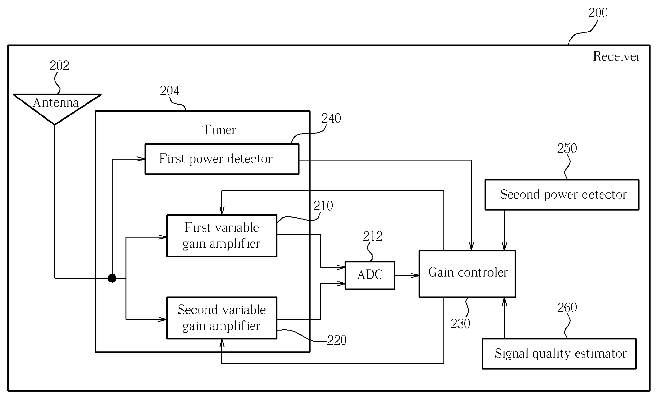
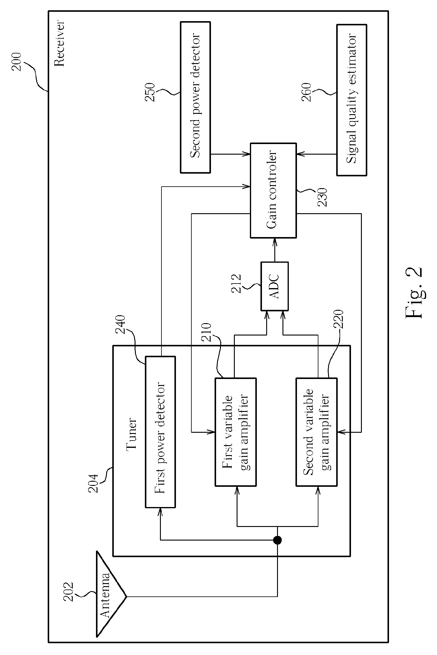
[0017]Please refer to FIG. 2. FIG. 2 is a simplified block diagram illustrating a receiver 200 according to an embodiment of the present invention. As shown in FIG. 2, the receiver 200 compri...


PUM


Abstract

A gain control method which includes setting a first initial gain value to a first variable gain amplifier; measuring a first power value corresponding to incoming signals; measuring a second power value corresponding to a target signal; and resetting the first initial gain value according to the first power value and the second power value. Another gain control method is also disclosed, which includes updating a gain value of a first variable gain amplifier by combining an adjustment value with the gain value according to a first tuning direction; obtaining a signal quality indicator; comparing the signal quality indicator with a reference signal quality indicator to generate a comparison result; and referring to the comparison result, further updating the gain value according to the first tuning direction or a second tuning direction opposite to the first tuning direction.

Description

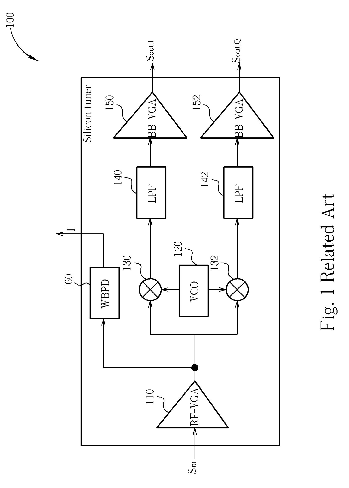
BACKGROUND OF THE INVENTION [0001]The present invention relates to a gain control mechanism, and more particularly, to an automatic gain control method and apparatus for a receiver.[0002]For Digital Video Broadcasting (DVB) receivers supporting terrestrial (DVB-T) or handheld (DVB-H) transmissions, more and more receivers are adopting silicon tuners instead of “can” tuners in order to reduce power consumption and circuit layout area. What's more, many silicon tuners are adopting direct conversion receiver (DCR) architecture for reducing the number of components and production cost.[0003]Please refer to FIG. 1. FIG. 1 is a simplified block diagram illustrating a silicon tuner with DCR architecture 100. As shown in FIG. 1, the typical silicon tuner with DCR architecture 100 includes a radio frequency voltage gain amplifier (RF-VGA) 110, a voltage-controlled oscillator (VCO) 120, an in-phase mixer 130, a quadrature mixer 132, an in-phase low-pass filter (LPF) 140, a quadrature low-pass...

Claims


Application Information

Patent Timeline
Patent Type & Authority Applications(United States)
IPC IPC(8): H04B1/06
CPCH03G3/3068H04N21/4263H04N5/52H04N5/4401H04N21/426
Inventor LIN, CHE-LICHOU, HUA-SHANWU, TSUNG-HAN
Owner MEDIATEK INC
Learn More