
Method for setting actual opertation frequency of memory and setting module thereof

a technology of memory and frequency, applied in the field of setting the frequency of memory and the setting module thereof, can solve the problems of increasing the difficulty of user frequency setting, frequency, and difficulty in setting the frequency, and achieve the effect of simplifying the process of setting the frequency of memory and facilitating the completion of overfrequency setting

Inactive Publication Date: 2009-03-19
ASUSTEK COMPUTER INC
View PDF18 Cites 6 Cited by
  • Summary
  • Abstract
  • Description
  • Claims
  • Application Information

AI Technical Summary

Benefits of technology

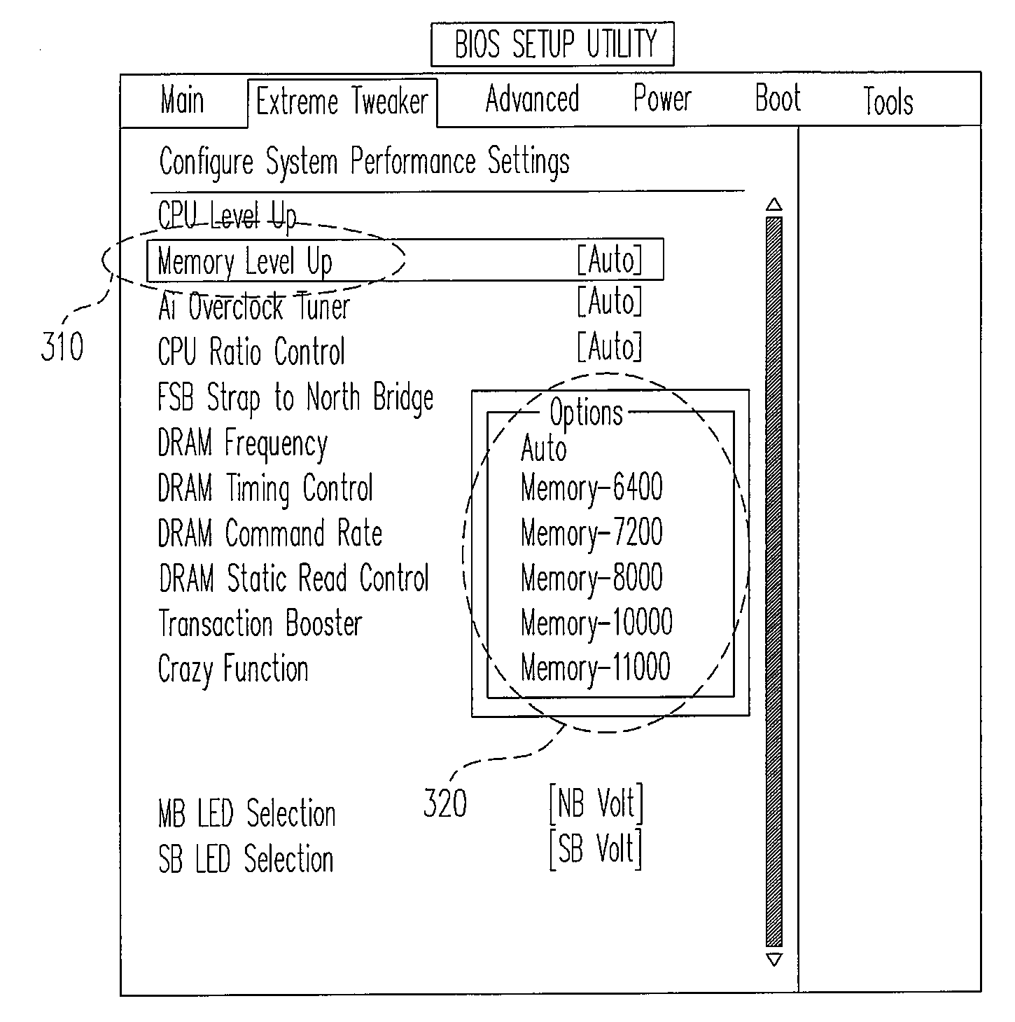
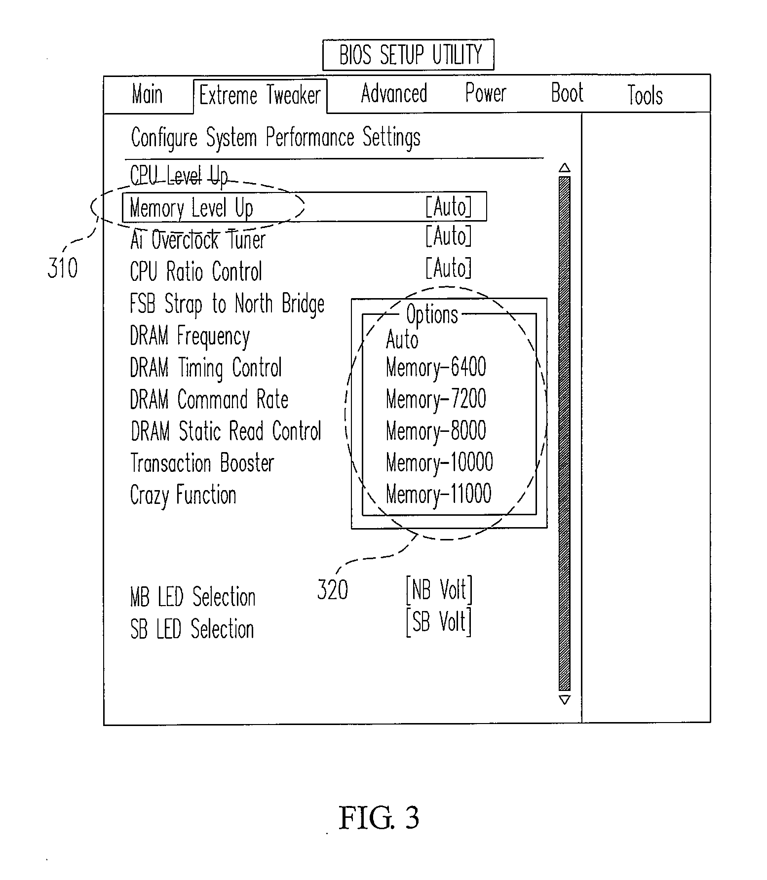
[0008]The invention provides a method for setting an operation frequency of a memory and a setting module thereof. An overfrequency setting menu is added into a setting picture of a basic input output system (BIOS), and then a user can directly set the operation frequency of the memory via a model on the package of the memory, and he does not need to set additional parameters such as a front side bus (FSB) parameter. In this way, the process of setting the frequency of the memory is simplified, and the user can easily finish the overfrequency setting.
[0014]Since the function of the invention is integrated into the BIOS system, the BIOS system can be used to directly adjust the FSB parameter, the frequency of the CPU and the frequency of the memory. A user only needs to select a wanted memory model via the overfrequency setting option provided by a user interface, and the other parameters are automatically set in the invention. In this way, the process of setting the frequency of the memory is simplified for the user.

Problems solved by technology

Furthermore, the user also needs to consider parameters such as the internal frequency, the external frequency and the operation voltage of the CPU, and a common user cannot clearly know the setting relationship of the FSB parameter value, the frequency of the memory and the frequency of the CPU.
Therefore, the overfrequency setting cannot be successfully finished.
In the conventional main computer configuration on the market, the frequency of the memory should be proportional to the frequency of the CPU, and it cannot be randomly adjusted, which adds difficulty when the user sets the frequency.

Method used


Image

  • Method for setting actual opertation frequency of memory and setting module thereof
  • Method for setting actual opertation frequency of memory and setting module thereof
  • Method for setting actual opertation frequency of memory and setting module thereof

Examples


Embodiment Construction

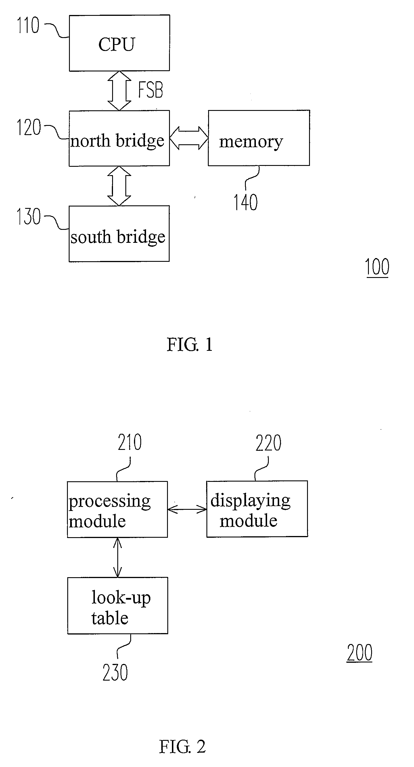
[0020]FIG. 1 is a schematic diagram showing a computer system configuration according to one embodiment of the invention. As shown in FIG. 1, a computer system configuration 100 includes a central processing unit (CPU) 110, a north bridge 120, a south bridge 130 and a memory 140. A bus between the north bridge 120 and the CPU 110 is a front side bus (FSB). Since data transmission between the CPU 110 and the south bridge 130, the north bridge 120 and the memory 140 is realized via the FSB, the transmission speed of the FSB affects the operation performance of the whole system. The operation frequency of the CPU 110 is proportional to the operation frequency of the FSB, and it usually is set via an external frequency parameter and a multiplier parameter.

[0021]In the main computer configuration (such as Intel), the operation frequencies of the CPU 110, the FSB and the memory 140 are corresponding to each other. The operation frequency values of the memory that are supported by various ...


PUM


Abstract

A method for setting an actual operation frequency of a memory is provided. The method includes the following steps. First, a memory model list is provided for selecting a memory model. Then, an estimation operation frequency of the memory is obtained according to the selected model. Finally, the operation frequency of a front side bus (FSB) is adjusted and cooperated with a frequency transformation ratio to generate the actual operation frequency of the memory according to the estimation operation frequency.

Description

CROSS-REFERENCE TO RELATED APPLICATION[0001]This application claims the priority benefit of Taiwan application serial no. 96134866, filed on Sep. 19, 2007. The entirety of the above-mentioned patent application is hereby incorporated by reference herein and made a part of specification.BACKGROUND OF THE INVENTION[0002]1. Field of the Invention[0003]The invention relates to a method for setting the frequency of a memory and, more particularly, to a method for setting the overfrequency of a memory and a setting module thereof.[0004]2. Description of the Related Art[0005]More and more memory module suppliers produce memory modules whose operation frequencies are higher than a common frequency range supported by a chip set. That is, the memory modules can be normally used only after the frequency of the chip set on a motherboard increases, and the operation frequency of a central processing unit (CPU) and other parameters are adjusted.[0006]Generally speaking, a user can set operation f...

Claims


Application Information

Patent Timeline
IPC IPC(8): G06F1/08
CPCG06F1/08
Inventor LIN, BING-MINHO, CHIN-FUWANG, YU-SHENGCHOU, YEN-TING
Owner ASUSTEK COMPUTER INC
Learn More