Methods and apparatus for encoding and decoding cyclic codes by processing multiple symbols per cycle

a cyclic code and cycle technology, applied in the field of encoding and decoding of cyclic codes, can solve the problems of high clock rate, unachievable, undesirable or unachievable, etc., and achieve the system complexity of providing varying clock rates, and the error characteristics of the channel/medium

Inactive Publication Date: 2009-03-19
LEE JOSEPH SCHWEIRAY
View PDF5 Cites 22 Cited by
  • Summary
  • Abstract
  • Description
  • Claims
  • Application Information

AI Technical Summary

Problems solved by technology

In many semiconductor designs, such a high clock rate is undesirable or unachievable.
Since it adds to the system complexity to provide varying clock rates, it is not desirable to use the prior-art encoder in a system with varying data transfer rate.
Further, the error characteristics of the channel / medium may also vary across time or different applications, and thus may require different error correction codes to achieve different levels of data integrity.

Method used


Image

  • Methods and apparatus for encoding and decoding cyclic codes by processing multiple symbols per cycle
  • Methods and apparatus for encoding and decoding cyclic codes by processing multiple symbols per cycle
  • Methods and apparatus for encoding and decoding cyclic codes by processing multiple symbols per cycle

Examples


first embodiment

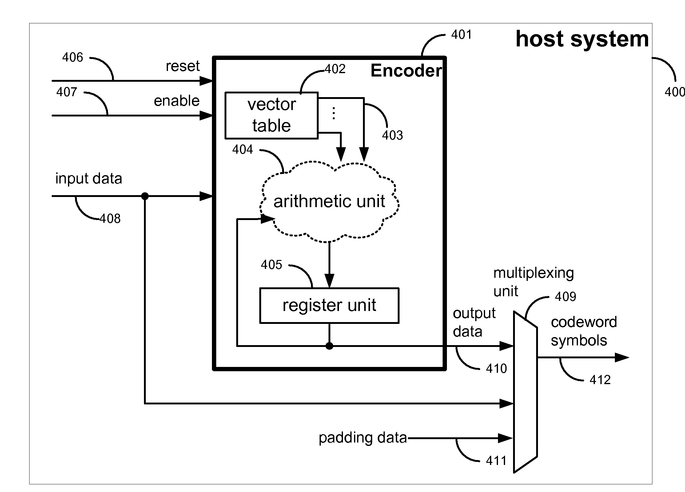
[0042]The Encoder of the first embodiment is described as follows. As illustrated in FIG. 4, the Encoder comprises a vector table (402), a register unit (405) and an arithmetic unit (404). The vector table outputs M vectors (403) each of which comprises the n−k coefficients of a pre-calculated remainder polynomial obtained from dividing a corresponding Identity Polynomial (defined below) by the generator polynomial g(X) of the cyclic code. The register unit is capable of storing n−k symbols. The Encoder further comprises an input data signal (408) via which the host inputs M message symbols per cycle to the Encoder, an output data signal (410) outputting the content of the register unit as the output of the Encoder, a reset signal (406) which clears the register unit to zero when asserted, and optionally an input enable signal (407) which enables the register unit to latch the output of the arithmetic unit at the end of a cycle when asserted. Before the encoding operation begins, th...

third embodiment

[0074]The Decoder of the third embodiment is described as follows. As illustrated in FIG. 10, the Decoder comprises an input “data size” signal (1025) via which the host inputs the value of Mj in each cycle of the decoding operation, and a multiplexing unit (1026) which, with its select input coupled with the input data size signal, outputs M+1 vectors (1015 to 1017), whereby Mj+1 of these output vectors are selected from the Root Vectors while the other (M−Mj) output vectors are zero vectors. The M+1 vectors output by the multiplexing unit may be indexed from 0 to M, whereby the output vectors indexed 0 to M−1 (1015, 1016) are sent to the M scalar multipliers (1012, 1013) to be each multiplied by one of the received symbols (1009, 1010) while the output vector indexed M (1017) is sent to the vector multiplier (1014) to be multiplied symbol-wise with the Register Feedback Vector (1007). For a particular value of Mj, the multiplexing unit selects the Mj+1lowest Root Vectors, i.e. Roo...

fourth embodiment

[0077]The Encoder of the fourth embodiment is described as follows. FIG. 11 illustrates an exemplary Encoder, wherein the vector table (1102) is a programmable memory device coupled with an input vector table loading signal (1124) via which the host may load a different set of IR Vectors into the vector table before the encoding operation of a codeword.

[0078]Preferably, the cyclic codes for which this Encoder is to be configured have the same symbol size wherein the symbols may be represented by the same Galois Field, such that the Galois Field arithmetic operators such as the scalar multipliers operate correctly for different cyclic codes. Further, the exemplary Encoder illustrated in FIG. 11 has the structural capacity for cyclic codes where the parity of each codeword has the maximum length of n−k symbols. More specifically, the vector table has the capacity of storing M IR Vectors of n−k symbols, each signal (1115 to 1117) carrying an IR Vector is n−k symbols wide; the scalar mu...


PUM


Abstract

Provided are an encoder and a syndrome computer for cyclic codes which process M codeword symbols per cycle where M is greater than or equal to one, whereby the encoder and syndrome computer optionally further provide the configurability of a different M value for each cycle and/or the configurability of a different cyclic code for each codeword. Further provided is a hybrid device which provides the configurability of two modes of operation, whereby in one mode, the hybrid device functions as the encoder as provided above and, in the other mode, the hybrid device functions as the syndrome computer as provided above, with the majority of the components of the hybrid device being shared between the encoding function and the syndrome computing function.

Description

PRIORITY APPLICATION[0001]This application claims the benefit under 35 U.S.C. 119(e) of U.S. Provisional Application 60 / 993,359 (filed Sep. 13, 2007). The entire disclosure of this application is hereby incorporated by reference herein.COPYRIGHT RIGHTS[0002]A portion of the disclosure of this patent document contains material that is subject to copyright protection. The copyright owner has no objection to the facsimile reproduction by any one of the patent document or the patent disclosure, as it appears in the Patent and Trademark Office patent file or records, but otherwise reserves all copyright rights whatsoever.BACKGROUND OF THE INVENTION[0003]1. Field of the Invention[0004]The present invention is related to the encoding and decoding of error correction codes in data communications and / or data storage systems, and in particular, to encoding and syndrome computation for cyclic codes.[0005]2. Description of the Related Art[0006]Error correction coding is often used in data commu...

Claims


Application Information

Patent Timeline
Patent Type & Authority Applications(United States)
IPC IPC(8): G06F11/10
CPCH03M13/15H03M13/1515H03M13/6561H03M13/611H03M13/152
Inventor LEE, JOSEPH SCHWEIRAY
Owner LEE JOSEPH SCHWEIRAY
Why Eureka
Try Eureka