Rifle mount

a technology of rifle mounts and accessories, applied in the field of rifle mounts, can solve the problems of insufficient rigidity, inconvenient installation, and inability to adapt to the actual system of bolt action rifles, and achieve the effect of limiting the inherent accuracy of the host weapon system

Inactive Publication Date: 2009-03-26
PRITCHETT PRESTON L
View PDF27 Cites 20 Cited by
  • Summary
  • Abstract
  • Description
  • Claims
  • Application Information

AI Technical Summary

Benefits of technology

[0012]The recoil lug rifle mount of the present invention is designed to work with receivers that have integral rails or mounts. The recoil lug rifle mount of the present invention is held in place by the inherent compression-tension / friction between the barrel and receiver when tightened, therefore eliminating addition compression pins, indexing or mechanical means to maintain alignment to the host action / rifle. The recoil lug rifle mount of the present invention will not degrade, interfere, or limit the inherent accuracy of the host weapon system. Every bolt rifle or rifle that needs more rail space or needs a more rigid accessory mount will benefit from the recoil lug rifle mount of the present invention.

Problems solved by technology

However, it has been found that current accessory mounts affixed to the stock or hand guards of firearms are susceptible to inaccuracies due to being jarred and jolted during the course of regular operations and especially during firing.
The current systems made for the bolt action rifles tend to be configured too far forward on the weapon and are not sufficiently rigid.
Moreover, they oftentimes include complex and intricate attachment mechanisms.
In addition, such accessory mounts often detract from the original ergonomics of the firearm.

Method used


Image

  • Rifle mount
  • Rifle mount
  • Rifle mount

Examples


Embodiment Construction

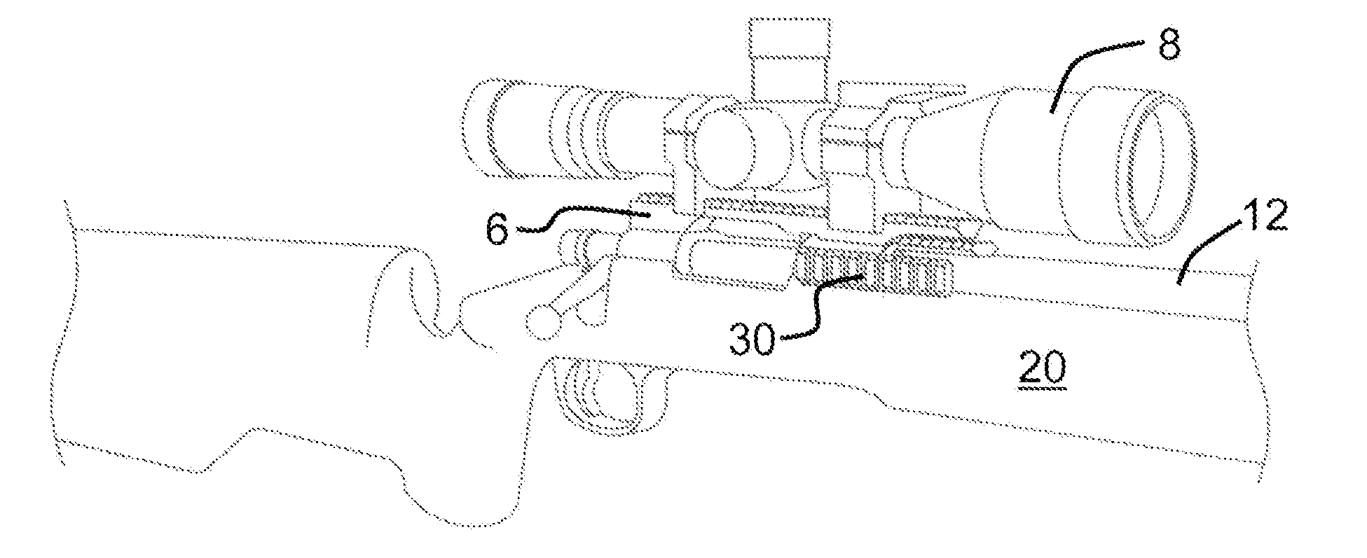
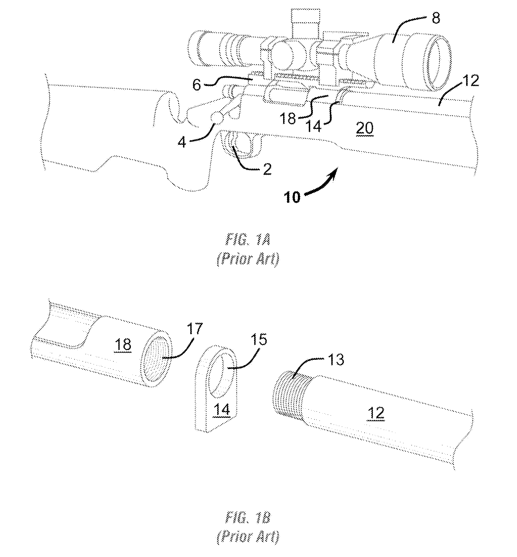
[0023]With reference to FIGS. 1 and 2, current hunting and sniper rifles 10 typically comprise a rifled barrel 12 having an attached firing mechanism and housed in a rifle stock 20. In bolt action rifles as depicted, the firing mechanism typically include a firing bolt 4 slidably coupled with a receiver mechanism 18. A trigger assembly 2 is utilized to actuate a firing pin within the bolt action. In addition, such rifles oftentimes include an optical scope 8 that is typically positioned above the receiver 18 and configured parallel to the gun barrel 12, so that the scope line of sight extends generally parallel to the line of fire extending from the barrel 12. The optical scope 8 is fixably attached to the receiver 18 by means of a primary mount 6. Typically, the primary mount 6 is fixably attached to the receiver 18 by means of screw fasteners. The primary mount 6 usually includes a rail system upon which the optical scope 8 can be demountably attached.

[0024]The barrel 12 of the ex...


PUM


Abstract

The rifle mount of the present invention comprises a recoil lug having an aperture formed therethrough, wherein the lug further includes about its periphery at least one accessory mounting point. The recoil lug rifle mount of the present invention is a one piece mounting system which has an integral recoil lug that is sandwiched between the receiver and barrel creating a more rigid mounting system that is in an ergonomic operating area.
In a preferred embodiment the improved recoil lug rifle mount of the present invention includes three accessory mounts disposed about the periphery of the lug. The recoil lug rifle mount of the present invention also includes extension wings which align the mounting rails with the barrel of the rifle. The recoil lug rifle mount of the present invention is operable to hold a variety of interchangeable accessory devices (e.g., aiming devices, laser range finding devices, flashlight devices) in a rigid yet more accessible area for the operator. In a preferred embodiment of the present invention, the accessory mounts comprise standardized mil spec (i.e., “Picatinny”) mounting rails for interchangeability of current technological accessory items known in public and military arenas, such as a flashlight, laser, night vision device, aiming device etc.

Description

CROSS-REFERENCE TO RELATED APPLICATION[0001]This application claims the benefit of and priority to a U.S. Provisional Patent Application No. 60 / 995,323 filed Sep. 26, 2007, the technical disclosure of which is hereby incorporated herein by reference.BACKGROUND OF THE INVENTION[0002]1. Technical Field of the Invention[0003]The present invention broadly relates to apparatus for mounting accessory sighting and aiming devices to firearms. More particularly, the present invention relates to an accessory mount fitted around the barrel of a rifle and configured to support a series of accessory devices simultaneously.[0004]2. Description of the Related Art[0005]Rifles have long included sights and optical scopes for accurate aiming of the rifle at a target. Moreover, mechanisms for mounting optical telescopes and similar aiming devices on firearms are well developed in the art. In more recent years, the increasing use technological accessories in conjunction with firearms has generated a ne...

Claims


Application Information

Patent Timeline
Patent Type & Authority Applications(United States)
IPC IPC(8): F41C27/00
CPCF41G11/003F41G1/387
Inventor PRITCHETT, PRESTON L.
Owner PRITCHETT PRESTON L
Why Eureka
Try Eureka