Self Starting Method and an Apparatus for Sensorless Commutation of Brushless Dc Motors

a brushless dc motor and self-starting technology, which is applied in the direction of electronic commutators, synchronous motor starters, dynamo-electric machines, etc., can solve the problems and achieve the effect of decreasing the reliability of the system

Active Publication Date: 2009-03-26
DE FOUR RONALD
View PDF14 Cites 22 Cited by
  • Summary
  • Abstract
  • Description
  • Claims
  • Application Information

AI Technical Summary

Benefits of technology

[0012]The present invention is based fundamentally, on the existence of voltage vectors that occupy the stator space of a Brushless DC motor. The sum of the two applied phase voltage vectors and the BEMF phase vector of the unenergized phase winding, produce the resultant voltage vector, the angle of which made with the real axis is used to commutate phase windings for efficient motor operation. This sensorless commutation technique utilizing voltage vectors and more precisely, the angle made by the resultant voltage vector is innovative, ground-breaking and revolutionary to the field of sensorless commutation of Brushless DC motors. It utilizes the same Digital Signal Processor (DSP) which is used to supply the control waveforms for motor energization, to compute the phase and resultant voltage vectors and the angle that the resultant voltage vector makes with the real axis, thereby eliminating the need for additional signal conditioning electronic circuitry, which components undergo aging and fail with time, thus decreasing the reliability of the system.

Problems solved by technology

It utilizes the same Digital Signal Processor (DSP) which is used to supply the control waveforms for motor energization, to compute the phase and resultant voltage vectors and the angle that the resultant voltage vector makes with the real axis, thereby eliminating the need for additional signal conditioning electronic circuitry, which components undergo aging and fail with time, thus decreasing the reliability of the system.
This said method of vector analysis as presented by Kovacs although mathematically correct, raises some fundamental issues when applied to electrical machine analysis.

Method used


Image

  • Self Starting Method and an Apparatus for Sensorless Commutation of Brushless Dc Motors
  • Self Starting Method and an Apparatus for Sensorless Commutation of Brushless Dc Motors
  • Self Starting Method and an Apparatus for Sensorless Commutation of Brushless Dc Motors

Examples


Embodiment Construction

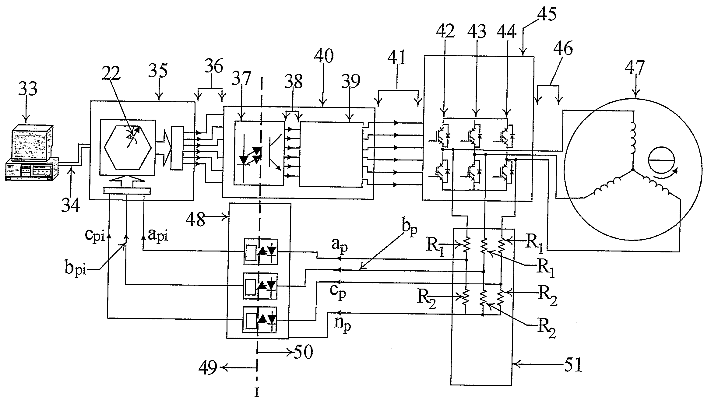
[0098]The commutation technique employed in the present invention, overcomes all of the disadvantages of the known prior art, namely that of BEMF Zero Crossing, BEMF Integration and the BEMF Third Harmonic Sensorless Commutation techniques. This said commutation technique of the present invention is sensorless and self-starting on load, thus making it superior to all known existing sensored and sensorless commutation techniques. Additionally this said technique is used for starting and running the motor.

[0099]This said technique, utilises a Digital signal Processor (DSP) to compute the stator phase voltage space vector, the rotation of which is dependent on the BEMF induced in the unenergized winding. As a result, this BEMF space vector sits on the rotor and provides rotor position information as the rotor begins to move. It utilises the angle that the BEMF Space Vector makes with the real axis to commutate phase windings and is easily applied to motors with any number of poles, pro...


PUM


Abstract

A method and an apparatus for determining rotor position information of a Brushless DC motor using the resultant voltage vector produced by addition of phase voltage vectors of the energised windings and the BEMF vector of the unenergised winding. This resultant voltage vector called the BEMF Space Vector rotates at same speed as the rotor and possesses rotor position information used to commutate phase windings. Phase voltage vectors for the computation of the BEMF Space Vector are obtained by referring scalar phase voltages in the electrical circuits to the magnetic axes of the magnetic circuits, since scalar and vector current magnitudes are equal. Angles that the BEMF Space Vector makes with the real axis are measured to commutate the phase windings. This technique is referred to as the De Four BEMF Space Vector Resolver, used to efficiently start the motor from rest and commutate phase windings during normal operation.

Description

BACKGROUND OF THE INVENTION[0001]1. Technical Field of the Invention The present invention which is self-starting, relates to the field of brushless permanent magnet motors and more particularly to brushless permanent magnet motors in DC operation, not having position sensors for detecting the rotational position of a permanent magnet motor.[0002]2. Background Art[0003]The present invention relates to a technique for efficient starting and commutation of a multi-phase Brushless DC motor under all load conditions without rotor position sensors.[0004]The Brushless DC (BLDC), motor is an, inverted brush DC motor in construction. The armature coils in the brush dc motor is transferred to the stator in the BLDC motor and the fixed magnets in the brush DC motor are transferred to the rotor in the BLDC motor. This design eliminates the need for the mechanical commutators and brushes which function is executed by transistors which act as switches.[0005]The motor is powered by turning on two...

Claims


Application Information

Patent Timeline
Patent Type & Authority Applications(United States)
IPC IPC(8): H02P6/18
CPCH02P6/20H02P6/182
Inventor DE FOUR, RONALD
Owner DE FOUR RONALD
Why Eureka
Try Eureka