Rotary electric motor having both radial and axial air gap flux paths between stator and rotor segments

a technology of rotary electric motors and air gap flux paths, which is applied in the direction of dynamo-electric machines, magnetic circuit rotating parts, and shape/form/construction of magnetic circuits, to achieve the effects of low flux loss, high torque capability, and optimized magnetic potential gradien

Inactive Publication Date: 2005-05-10
BLUWAV SYST LLC
View PDF13 Cites 110 Cited by
  • Summary
  • Abstract
  • Description
  • Claims
  • Application Information

AI Technical Summary

Benefits of technology

[0005]The Maslov et al. applications recognize that isolation of the electromagnet groups permits individual concentration of flux in the magnetic cores of the groups, with low flux loss and no deleterious transformer interference effects with other electromagnet members. Operational advantages can be gained by configuring a single pole pair as an isolated electromagnet group. Magnetic path isolation of the individual pole pair from other pole groups eliminates a flux transformer effect on an adjacent group when the energization of the pole pair windings is switched.
[0006]Copending related U.S. patent application of Maslov et al., Ser. No. 09 / 966,101 describes benefits to be gained from utilization of three dimensional aspects of motor structure. Advantages are recognized from the use of materials such as a soft magnetically permeable medium that is amenable to formation of a variety of particular shapes. For example, core material may be manufactured from soft magnet grades of Fe, SiFe, SiFeCo, SiFeP powder material, each of which has a unique power loss, permeability and saturation level. Core geometries and core dimensions of stator elements, with relevant tolerances, can be formed without the need to form laminations and thus optimize the magnetic potential gradient developed between coupled poles of rotor permanent magnets and stator electromagnets. A structural configuration is disclosed wherein axially aligned stator poles and axially aligned rotor magnets provide highly concentrated flux distribution. Such configuration provides a greater number of poles with the same individual active air gap surface areas and / or greater total active air gap surface area than conventional motors having the same air gap diameter.
[0007]In summary, concentration of flux, maximization of flux, minimization of flux loss and transformer interference effects, are all contributing factors in the attainment of efficient motor operation with high torque capability. Motor structural configurations in which multiple poles are in axial alignment to provide efficient operation at high torque output have been described in the above-identified copending applications. Such arrangements, due to the relatively great volume occupied by the large number of stator core elements and rotor poles, are advantageous for use in environments in which space and weight considerations are not at a premium. There is a continuing need for motor structural configurations that provide these improved attributes as well as economy of size and geometry.
[0008]The above-identified copending Maslov et al. application, addresses these needs by development of motor structural configurations to increase the surface areas of opposing stator poles and rotor poles across a plurality of air gaps. The relatively larger surfaces in which flux can be concentrated promote high torque capacity. These concepts are further structurally developed in the present invention.
[0009]Advantages of the present invention are achieved, at least in part, by increasing those surface areas of stator and rotor elements that interact to produce electromotive force. The structural features of one such configuration of the invention are embodied in a motor that comprises a rotor and a stator in which a plurality of separated electromagnet core segments are disposed coaxially about an axis of rotation. The stator core segments form an annular stator ring bounded by an inner and outer diameter. The core segments are affixed, without ferromagnetic contact with each other, to a non-ferromagnetic support structure.
[0010]The rotor is configured in an annular ring that at least partially surrounds the annular stator to define a radial air gap and a pair of axial air gaps through which flux paths are produced to generate electromotive force. The rotor ring is formed of magnetically permeable material with a U-shaped cross-sectional configuration having sides joined by a cross portion. A plurality of permanent magnets are distributed along inner surfaces of the rotor sides and cross portion, thereby facing the two axial air gaps and the radial air gap. The permanent magnets successively alternate in polarity along the circumference of the rotor ring surfaces. The permanent magnets on the two side portions are respectively in axial alignment with each other and have opposite magnetic polarities. Each relatively flat permanent magnet is a magnetic dipole having one magnetic polarity at its surface facing an air gap and the opposite magnetic polarity at its surface mounted to the side portion or cross portion. The permanent magnets mounted on the side portions thus have magnetic polar orientation in the axial direction while the permanent magnets mounted on the cross portion have magnetic polar orientation in the radial direction.

Problems solved by technology

The progressive improvement of electronic systems, such as microcontroller and microprocessor based applications for the control of motors, as well as the availability of improved portable power sources, has made the development of more efficient electric motor drives a compelling challenge.

Method used


Image

  • Rotary electric motor having both radial and axial air gap flux paths between stator and rotor segments
  • Rotary electric motor having both radial and axial air gap flux paths between stator and rotor segments
  • Rotary electric motor having both radial and axial air gap flux paths between stator and rotor segments

Examples


Embodiment Construction

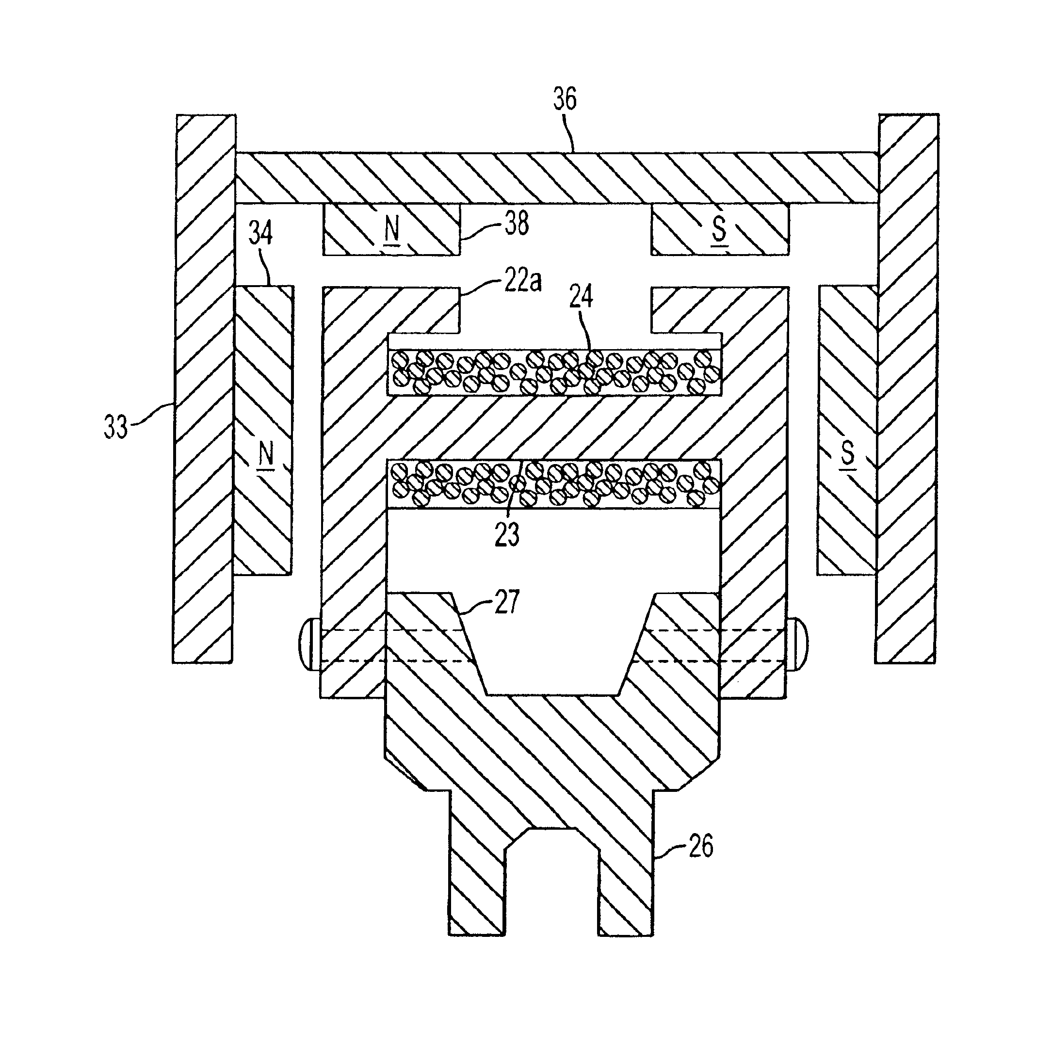
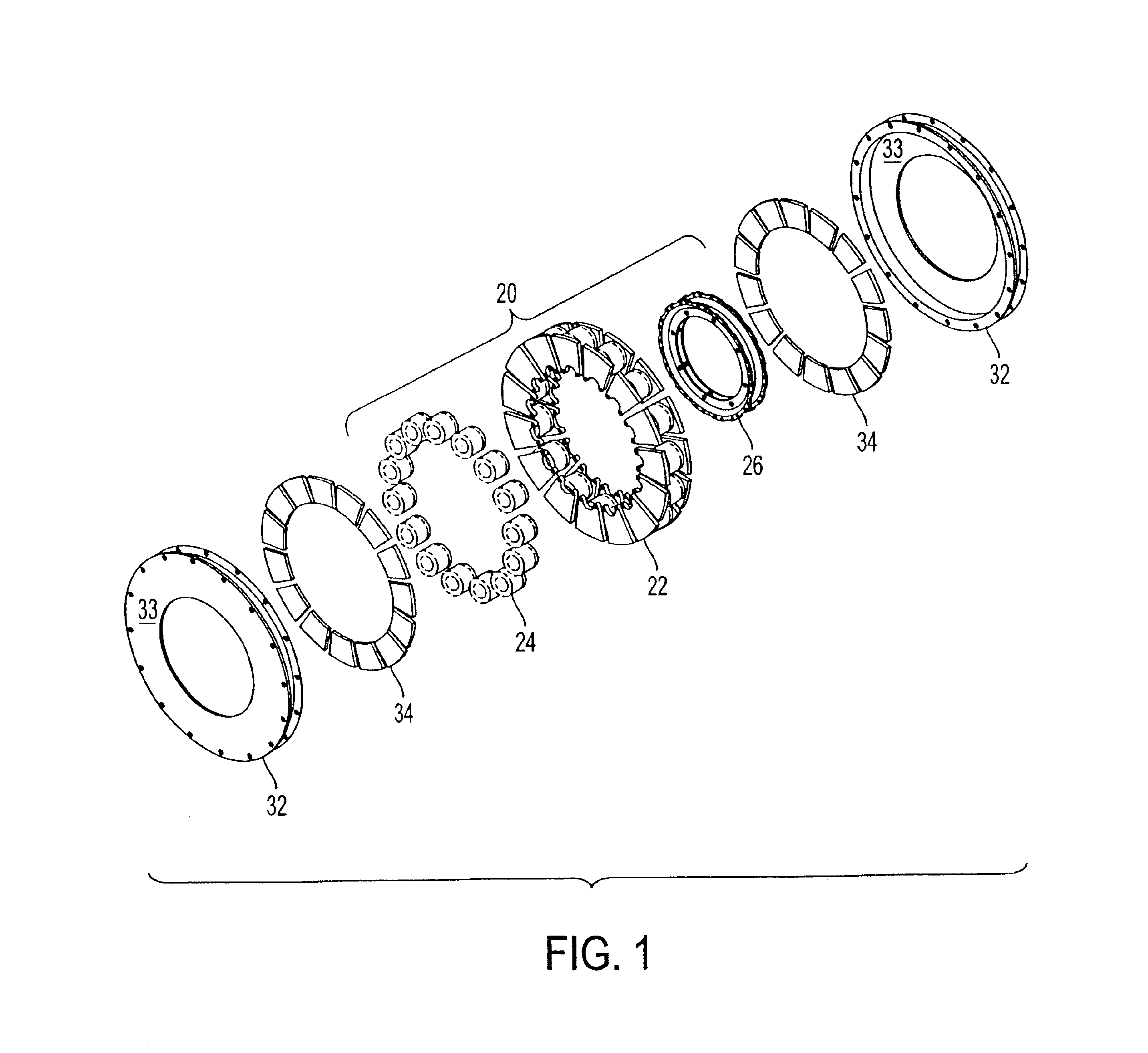
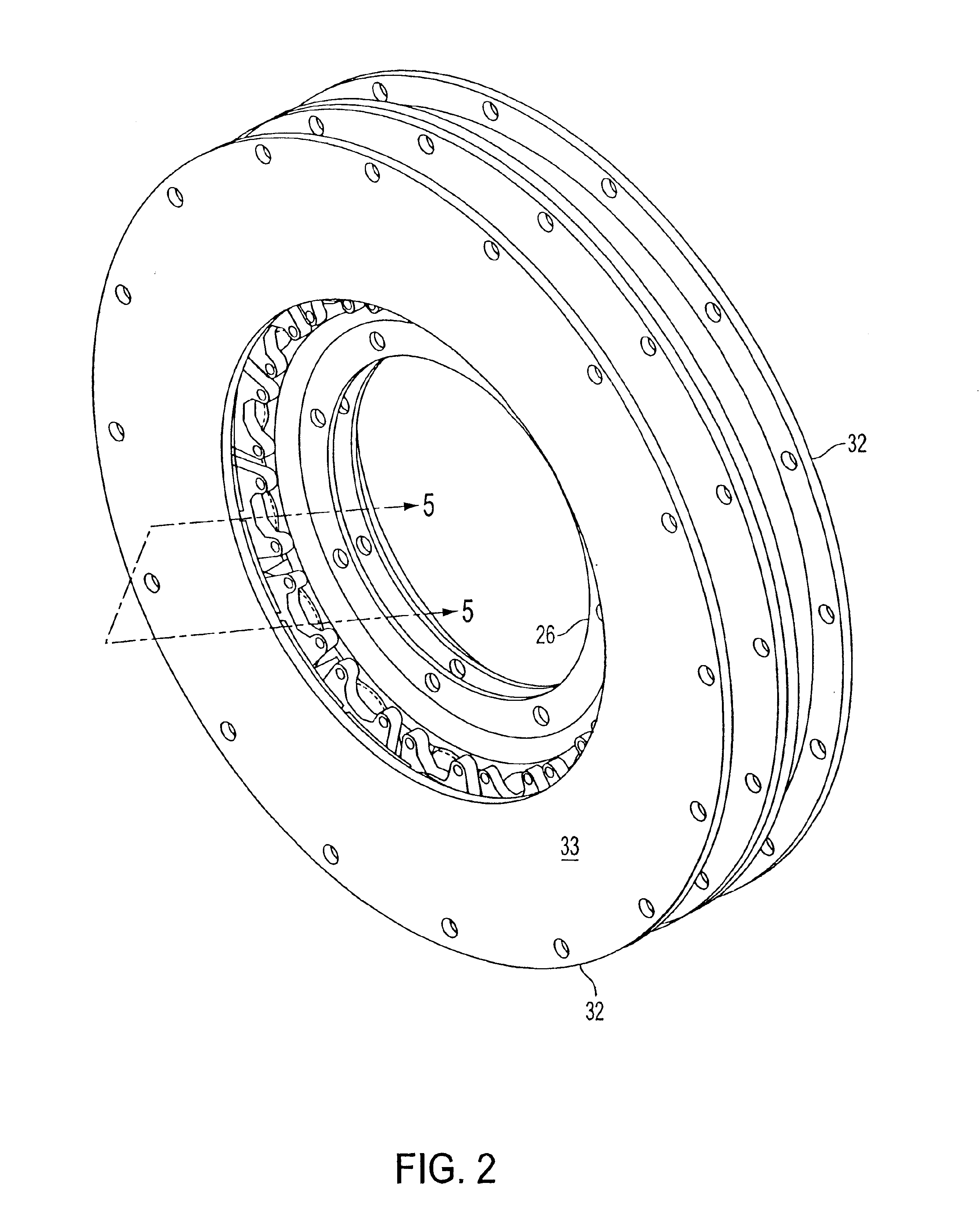
[0025]FIG. 1 is a three-dimensional exploded view illustrating components of the invention. The components in combination form the assembled motor construction illustrated in FIG. 2. For simplicity of explanation, elements that are not necessary for understanding the present invention have not been illustrated. Reference is made to the aforementioned copending applications for a more detailed description of such features. The elements indicated by bracket 20, when assembled, form a stator annular ring that is centered about an axis of rotation. The stator ring comprises a plurality of ferromagnetically isolated electromagnets having core portions 22 upon which are to be formed windings 24. Non-ferromagnetic ring 26 is a support structure for the individual electromagnets. A more detailed illustration of the stator ring construction is provided in FIG. 4. End portions 32 and permanent magnets 34, when assembled, form an annular ring centered about the axis of rotation and at least pa...


PUM


Abstract

In a rotary electric motor, a stator contains a plurality of separate electromagnet core segments disposed coaxially about an axis of rotation. The core segments are affixed, without ferromagnetic contact with each other, to a non-ferromagnetic support structure. The rotor is configured in a U-shaped annular ring that at least partially surrounds the annular stator to define two parallel axial air gaps between the rotor and stator respectively on opposite axial sides of the stator and at least one radial air gap. Permanent magnets are distributed on each inner surface of the U-shaped rotor annular ring that faces an air gap. A winding is formed on a core portion that links axially aligned stator poles to produce, when energized, magnetic poles of opposite polarity at the pole faces.

Description

RELATED APPLICATIONS[0001]This application contains subject matter related to copending U.S. application Ser. No. 09 / 826,423 of Maslov et al., filed Apr. 5, 2001 now U.S. Pat. No. 6,492,756, issued Dec. 10, 2002; copending U.S. application Ser. No. 09 / 826,422 of Maslov et al., filed Apr. 5, 2001, copending U.S. application Ser. No. 09 / 966,101 of Maslov et al., filed Oct. 1, 2001 now U.S. Pat. No. 6,617,746, issued Sep. 9, 2003; copending U.S. application Ser. No. 10 / 067,305, of Maslov et al., filed Feb. 7, 2002, now U.S. Pat. No. 6,710,502, issued Mar. 23, 2004; and copending U.S. application Ser. No. 10 / 134,365 of Maslov et al., filed Apr. 30, 2002, all commonly assigned with the present application. The disclosures of these applications are incorporated by reference herein.FIELD OF THE INVENTION[0002]The present invention relates to rotary electric motors, more particularly to motors having a plurality of permanent magnet rotor elements and ferromagnetically isolated stator elemen...

Claims


Application Information

Patent Timeline
Patent Type & Authority Patents(United States)
IPC IPC(8): H02K1/18H02K21/12H02K21/24H02K16/00
CPCH02K1/182H02K1/27H02K21/24H02K21/12H02K1/2786H02K21/22H02K1/2793H02K1/2791H02K1/2798
Inventor SOGHOMONIAN, ZAREHMASLOV, BORIS A.
Owner BLUWAV SYST LLC
Why Eureka
Try Eureka