Ink jet printing apparatus and ink jet printing method
a printing apparatus and ink jet technology, applied in printing and other directions, can solve the problems of image degradation, color stripe unevenness, and problem of bidirectional printing, and achieve the effect of reducing unevenness and high printing speed
- Summary
- Abstract
- Description
- Claims
- Application Information
AI Technical Summary
Benefits of technology
Problems solved by technology
Method used
Image

Examples
first embodiment
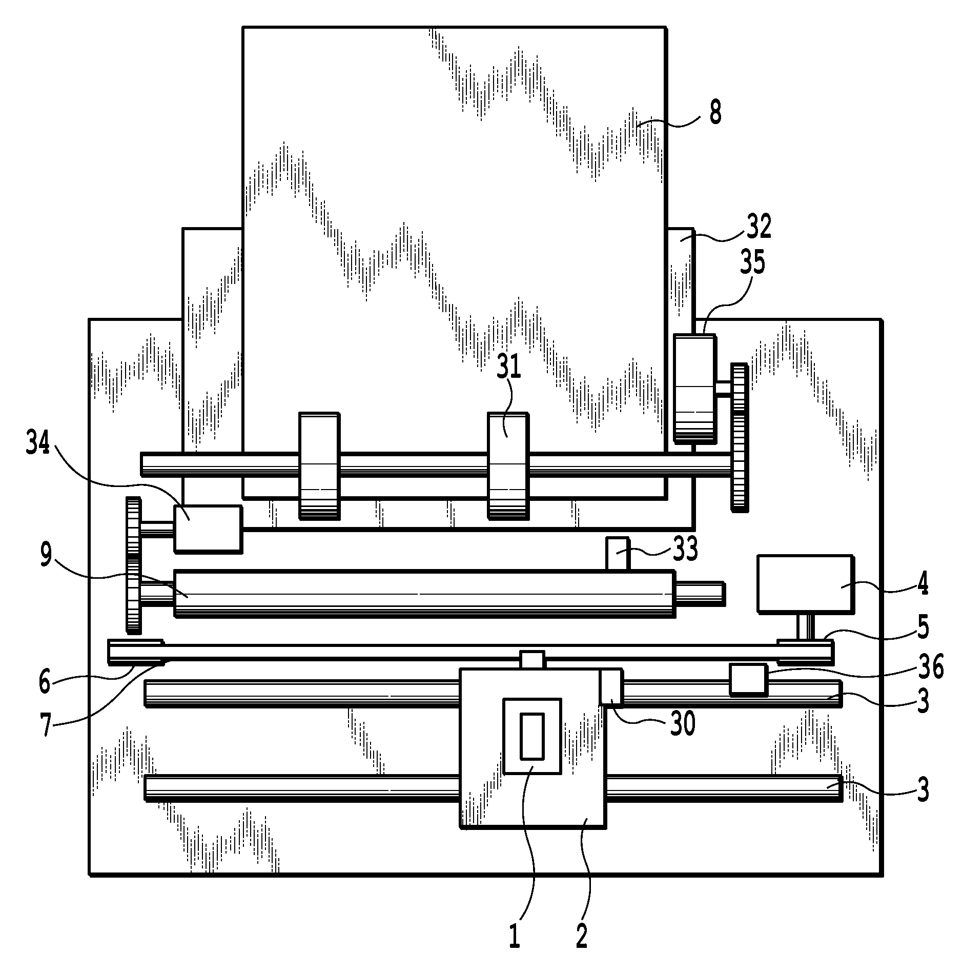
[0031]FIG. 1 is a schematic view illustrating an essential portion of an ink jet printing apparatus according to this embodiment. In FIG. 1, a cartridge 1 is mounted in a replaceable manner on a carriage 2. The cartridge 1 includes a print head section and an ink tank section, and the cartridge 1 is provided with a connector (not shown) through which signals for driving the head section are exchanged.
[0032]The cartridges 1 are mounted on the carriage 2 being positioned in place thereon. The carriage 2 is provided with a connector holder (electrical connecting section) for transmitting a driving signal and the like to each of the cartridges 1 through the connector. The carriage 2 is supported by a guide shaft 3 capable of reciprocating along the guide shaft 3 that is provided to the apparatus body extending along a main scanning direction. The carriage 2 is driven by a main scanning motor 4 via a drive mechanism such as a motor pulley 5, a driven pulley 6, and a timing belt 7. The po...
second embodiment
[0089]In the first embodiment, defining the width in the maximum eject port area of the black ink as “E”, and the width in the maximum eject port area of the color ink as “e”, the relationship between “E” and “e” is E=e×2 as illustrated in FIG. 4. However, the present invention is not limited to the above relationship. The width of “E” has only to be at least larger than the width of “e”.
[0090]FIG. 6 is a schematic view of a black tip 10 and a color tip 20 according to the second embodiment. In the second embodiment, as same as the first embodiment, the width of usable maximum area (maximum eject port area) in the ink eject port arrays 100 and 101, which are formed in the black tip 10, is defined as “E”. Also, the width of usable maximum area (maximum eject port area) in the ink eject port arrays 102 to 107, which are formed in the color tip 20, is defined as “e”. According to the second embodiment, when carrying out bidirectional printing using black nozzles and color nozzles, the ...
third embodiment
[0091]In the printing head according to the first embodiment, the eject port array of the color ink is disposed at the upstream side of the black ink eject port array. The present invention is not limited to the above arrangement. That is, in the printing head, the color ink eject port array may be disposed at the downstream side of the black ink eject port array.
[0092]FIG. 7 is a schematic view of the black tip 10 and the color tip 20 according to the third embodiment. FIG. 8 illustrates the printing operation according to the embodiment. The printing operation is the same as that of the first embodiment. The printing ratio of the eject port area “EA” (second nozzle group) is larger than that of the eject port area “EB” (first nozzle group). Particularly, the printing ratio X of the second nozzle group according to the embodiment is preferably within a range of 50%<X<80%.
[0093]With this arrangement, the printing ratio using the black first nozzle group, which overlaps with the colo...
PUM
 Abstract
Description
Claims
Application Information
 - Generate Ideas
- Intellectual Property
- Life Sciences
- Materials
- Tech Scout
- Unparalleled Data Quality
- Higher Quality Content
- 60% Fewer Hallucinations
Browse by: Latest US Patents, China's latest patents, Technical Efficacy Thesaurus, Application Domain, Technology Topic, Popular Technical Reports.
© 2025 PatSnap. All rights reserved.Legal|Privacy policy|Modern Slavery Act Transparency Statement|Sitemap|About US| Contact US: help@patsnap.com