Substrate transfer apparatus and method for controlling down flow

Inactive Publication Date: 2009-03-26
TOKYO ELECTRON LTD
View PDF7 Cites 23 Cited by
  • Summary
  • Abstract
  • Description
  • Claims
  • Application Information

AI Technical Summary

Benefits of technology

[0045]According to the present invention, the adherence of particles to the surface of a substrate in the transfer chamber can be prevented while suppressin

Problems solved by technology

These particles may adhere on the surface of the wafer during the transfer, and if the wafer is processed with the particles adhered, this may lead to a decrease in through put.
For example, in an etching process, excess etching may occur because of the particles adhered on the surface of the wafer act as a mask, and also in a film forming process, the quality of film may deteriorate because the film is developed with a particle adhered on the surface of the wafer acting as a core.
However, with the conventional technique, there has been an issue of not being able to sufficiently prevent the adherence of particles to the surface of the wafer because the speed of down flow is maintained at a constant speed and the relative speed of down flow against the wafer transferred downward is decreased depending on the speed of the downward transfer.
However, if the speed of the down flow is maintained at a constant speed even when the amount of out gas from the treated

Method used


Image

  • Substrate transfer apparatus and method for controlling down flow
  • Substrate transfer apparatus and method for controlling down flow
  • Substrate transfer apparatus and method for controlling down flow

Examples


Embodiment Construction

[0052]Preferred embodiments of the present invention will be explained in detail referring to the attached drawings. In addition, components described herein and drawings that have substantially the same functions are indicated by the same reference numbers and their explanation will be omitted.

[0053](Configuration Example of Apparatus for Transferring a Substrate)

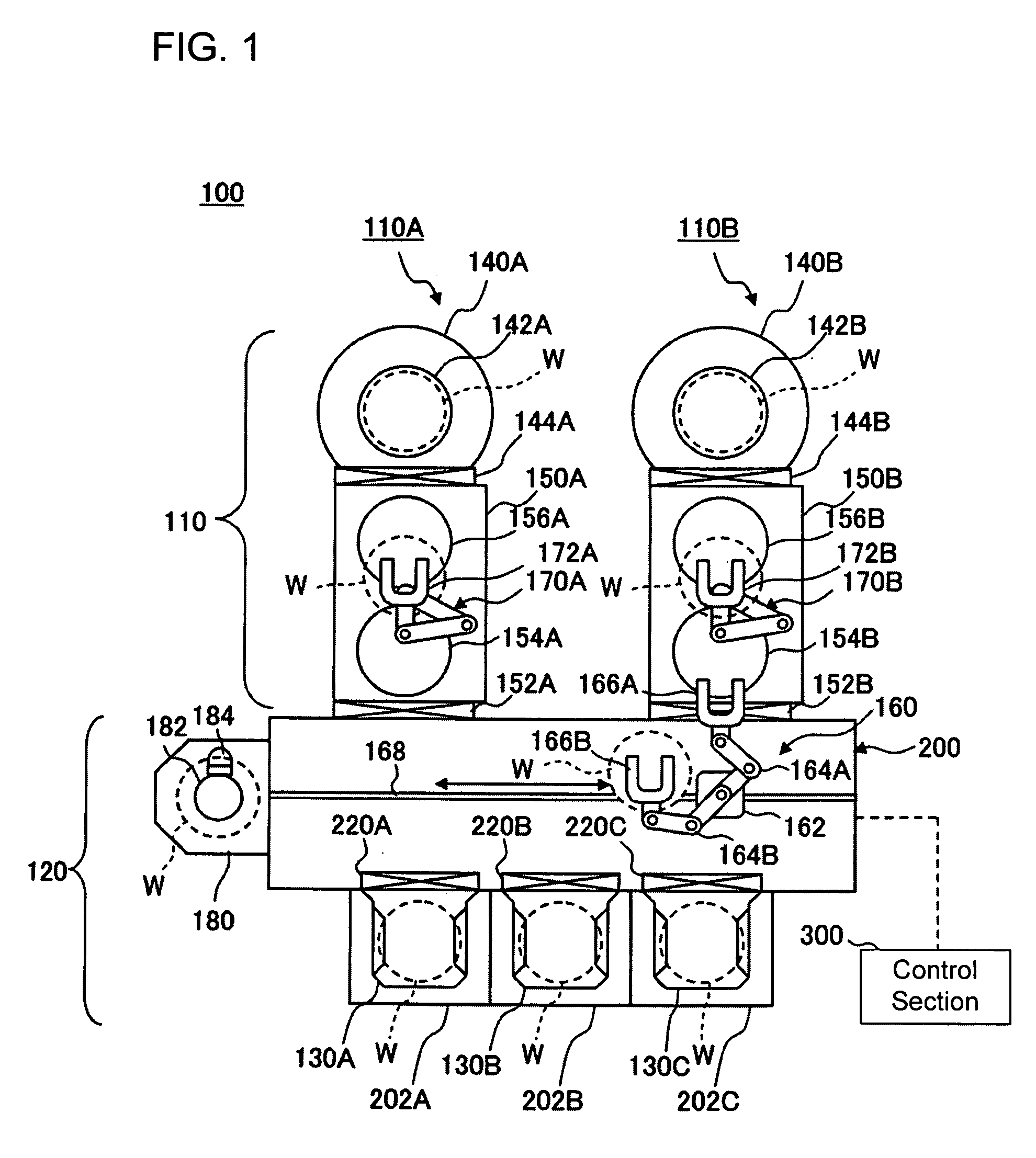
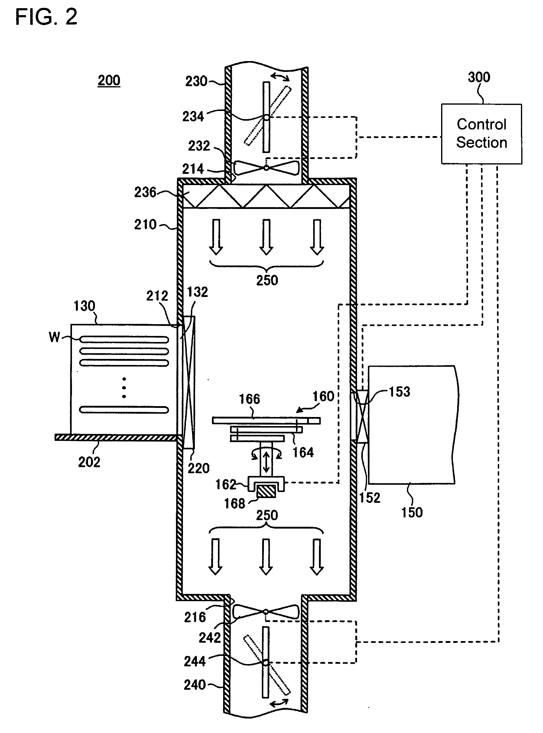
[0054]First, an embodiment in which an apparatus for transferring a substrate pertaining to the present invention is applied to a substrate treatment apparatus 100 for performing a predetermined treatment to a substrate, will be explained in detail referring to the figures. Here, explained is an example of the substrate treatment apparatus 100 in which one, or not less than two vacuum treatment units are connected to a transfer chamber and the treatment is performed by transferring the substrate to any of the vacuum treatment units from the transfer chamber. FIG. 1 is a cross section diagram illustrating an outline configu...


PUM


Abstract

The present invention relates to an apparatus for transferring a substrate through a gate for loading and unloading is provided, and includes a transfer chamber having the gate for loading and unloading the substrate, a transfer system, which is able to move up and down in the transfer chamber and transfers the substrate by accessing each gate, an adjustment section for a gas down flow, which produces the gas down flow in the transfer chamber and is able to adjust a speed of the gas down flow, and a control section for controlling the speed of the gas down flow using the movement speed of the substrate.

Description

TECHNICAL FIELD[0001]The present invention relates to an apparatus for transferring a substrate and method for controlling down flow.BACKGROUND OF THE INVENTION[0002]An apparatus for applying a predetermined process treatment, such as an etching process or film forming process, to a substrate to be treated, such as a glass substrate (for example, a liquid crystal substrate) or semiconductor wafer (hereinafter, referred merely as “wafer”) is provided with a treatment unit, which includes a treatment chamber connected to a load lock chamber for applying a predetermined treatment to the wafer, for example. Further, the apparatus is provided with a cassette container for storing an untreated wafer transferred into the apparatus or a treated wafer transferred outside the apparatus, and a transfer chamber having a transfer system for passing and receiving the wafer between the load lock chamber etc. In such a transfer chamber, a loading and unloading gate is provided respectively between ...

Claims


Application Information

Patent Timeline
IPC IPC(8): H01L21/67
CPCH01L21/67017H01L21/67778H01L21/67766Y10S414/135
Inventor MIYASAKA, MOTOKI
Owner TOKYO ELECTRON LTD
Why Eureka
Try Eureka