This helps you quickly interpret patents by identifying the three key elements:
Problems solved by technology
Method used
Benefits of technology
[0055]It is an advantage of the present invention that it can provide a compact apparatus for atomic layer deposition onto a substrate that is well suited to a number of different types of substrates and deposition environments.
[0056]It is a further advantage of the present invention that it allows operation, in preferred embodiments, under atmospheric pressure conditions.
[0057]It is yet a further advantage of the present invention that it is adaptable for deposition on a web or other moving substrate, including deposition onto a large area
Problems solved by technology
In practice, in any system it is difficult to avoid some direct reaction of the different precursors leading to a small amount of chemical vapor deposition reaction.
Self-saturating surface reactions make ALD relatively insensitive to transport non-uniformities, which might otherwise impair surface uniformity, due to engineering tolerances and the limitations of the flow system or related to surface topography (that is, deposition into three dimensional, high aspect ratio structures).
As a general rule, a non-uniform flux of chemicals in a reactive process generally results in different completion times over different portions of the surface area.
However, in spite of its inherent technical capabilities and advantages, a number of technical hurdles still remain.
However, it is difficult to obtain a reliable scheme for introducing the needed series of gaseous formulations into a chamber at the needed speeds and without some unwanted mixing.
In a typical ALD chamber the volume (V) and pressure (P) are dictated independently by the mechanical and pumping constraints, leading to difficulty in precisely controlling the residence time to low values.
Existing ALD approaches have been compromised with
Method used
Image
Click on the blue label to locate the original text in one second.
Reading with bidirectional positioning of images and text.
Examples
Example
[0082]The present description is directed in particular to diffusing elements forming part of, or cooperating within, an apparatus in accordance with the invention that delivers a fluid material to a substrate. It is to be understood that elements not specifically shown or described may take various forms well known to those skilled in the art.
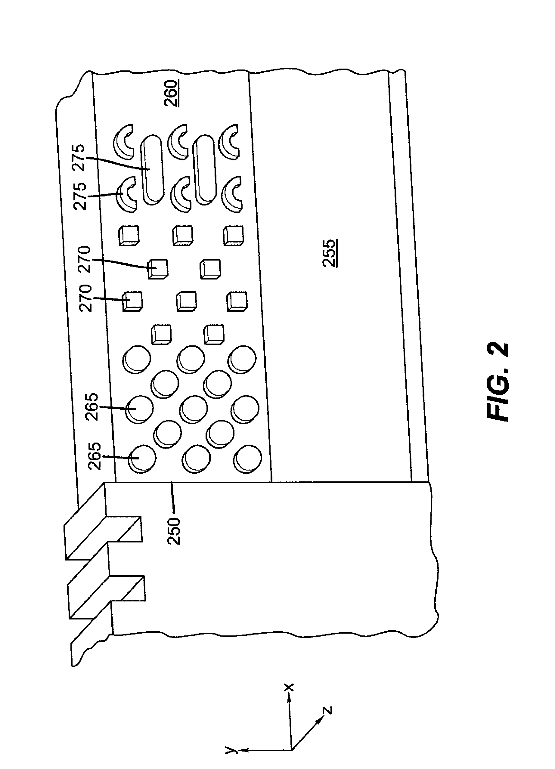
[0083]More particularly, this invention relates to a means of diffusing a gas flow from a source channel so that it exits uniformly over a longer linear region. While this method may be applied to a broad range of technologies, one important application is in the field of spatially dependent ALD.
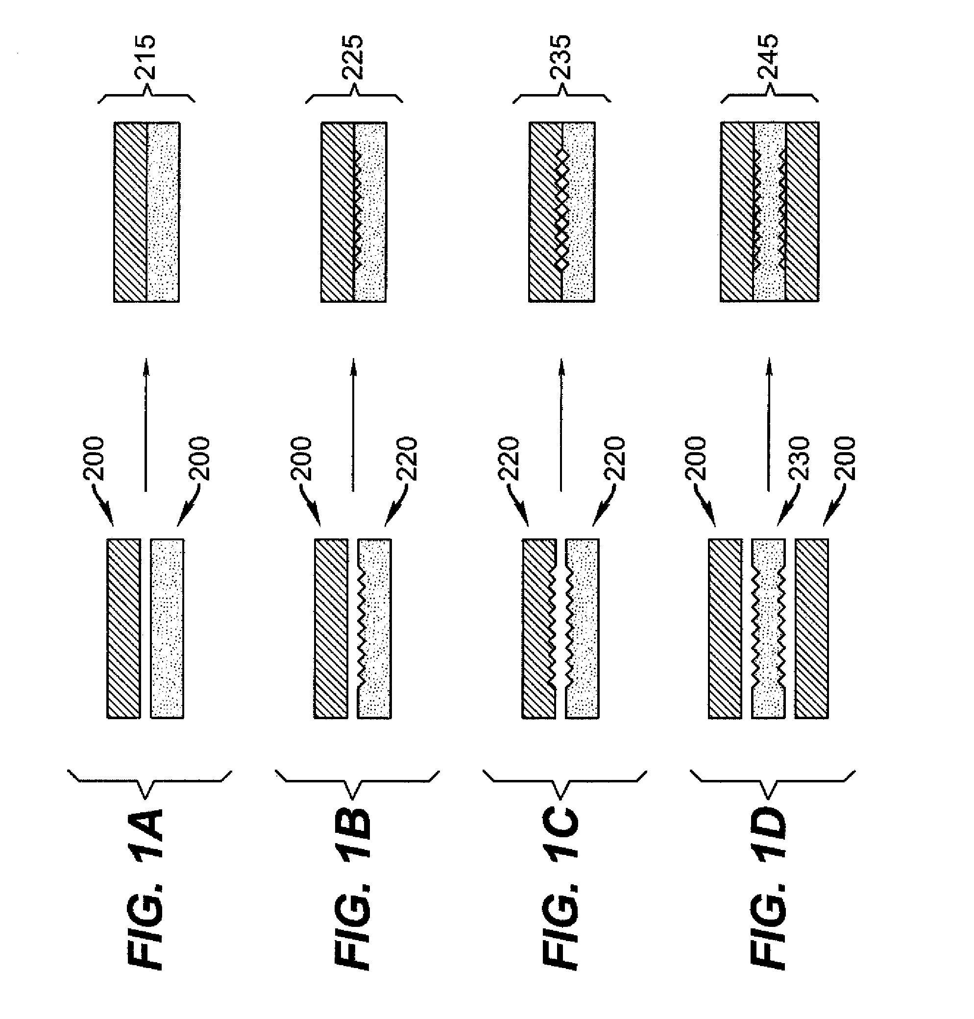
[0084]To suitably diffuse a flow of gas, an element that provides uniform flow backpressure over a linear region must be devised. In order to provide a restriction of flow, a channel needs to be created in which the open cross-section available for flow is very small. To provide suitable backpressures, the open cross-section for flow should have openin...
PUM
Property
Measurement
Unit
Temperature
aaaaa
aaaaa
Angle
aaaaa
aaaaa
Speed
aaaaa
aaaaa
Abstract
A delivery device for thin-film material deposition has at least first, second, and third inlet ports for receiving a common supply for a first, a second and a third gaseous material, respectively. Each of the first, second, and third elongated emissive channels allow gaseous fluid communication with one of corresponding first, second, and third inlet ports. The delivery device can be formed from apertured plates, superposed to define a network of interconnecting supply chambers and directing channels for routing each of the gaseous materials from its corresponding inlet port to a corresponding plurality of elongated emissive channels. The delivery device comprises a diffusing channel formed by a relief pattern between facing plates. Also disclosed is a process for thin film deposition. Finally, more generally, a flow diffuser and a corresponding method of diffusing flow is disclosed.
Description
CROSS-REFERENCE TO RELATED APPLICATIONS[0001]The present application is related to U.S. application Ser. No. 11 / 392,007, filed Mar. 29, 2006 by Levy and entitled, “PROCESS FOR ATOMIC LAYER DEPOSITION,” U.S. application Ser. No. 11 / 392,006, filed Mar. 29, 2006 by Levy and entitled “APPARATUS FOR ATOMIC LAYER DEPOSITION,” U.S. application Ser. No. 11 / 620,738, filed Jan. 8, 2007 by Levy and entitled “DELIVERY DEVICE FOR DEPOSITION,” U.S. application Ser. No. 11 / 620,740, filed Jan. 8, 2007 by Nelson et al. and entitled “DELIVERY DEVICE COMPRISING GAS DIFFUSER FOR THIN FILM DEPOSITION,” U.S. application Ser. No. 11 / 620,744, filed Jan. 8, 2007 by Levy and entitled, “DEPOSITION SYSTEM AND METHOD USING A DELIVERY HEAD SEPARATED FROM A SUBSTRATE BY GAS PRESSURE,” U.S. application Ser. No. ______ (94077), filed concurrently herewith by Kerr et al. and entitled, “DEPOSITION SYSTEM FOR THIN FILM FORMATION,” U.S. application Ser. No. ______ (docket 94079), filed concurrently herewith by Levy et ...
Claims
Application Information
Patent Timeline
Application Date:The date an application was filed.
Publication Date:The date a patent or application was officially published.
First Publication Date:The earliest publication date of a patent with the same application number.
Issue Date:Publication date of the patent grant document.
PCT Entry Date:The Entry date of PCT National Phase.
Estimated Expiry Date:The statutory expiry date of a patent right according to the Patent Law, and it is the longest term of protection that the patent right can achieve without the termination of the patent right due to other reasons(Term extension factor has been taken into account ).
Invalid Date:Actual expiry date is based on effective date or publication date of legal transaction data of invalid patent.