

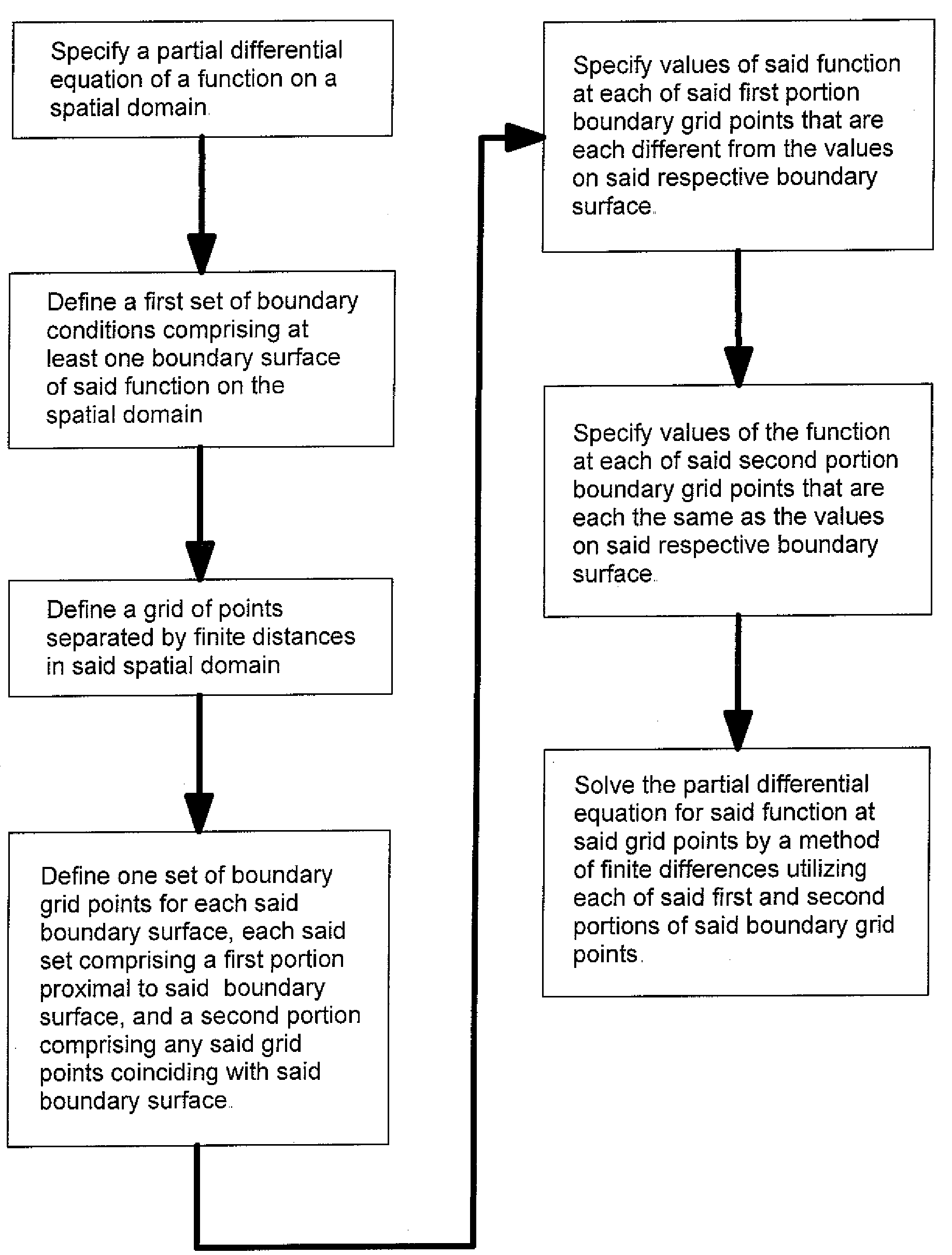
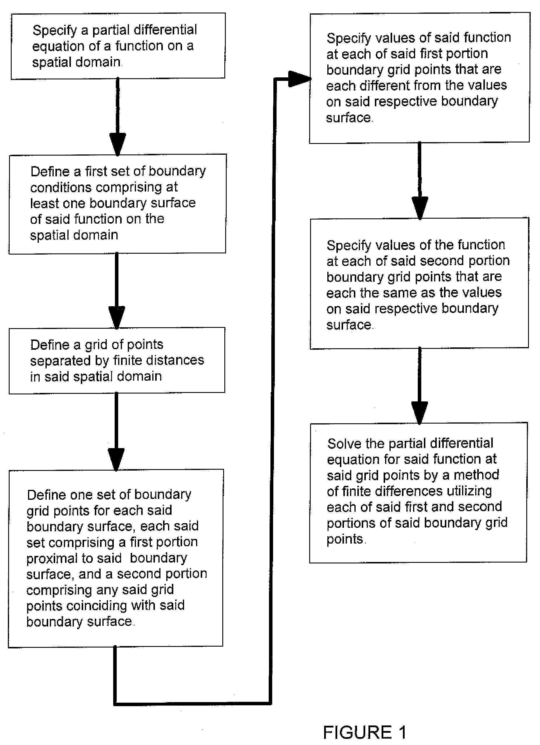
Finite differences methods
a finite difference and method technology, applied in the field of numerical analysis by finite difference methods, can solve the problems of increasing computer processing time and memory requirements, compromising one or more relative advantages of fd methods, and resulting cost, and achieves improved accuracy in solving, improved accuracy in the calculation of functions, and improved accuracy.
- Summary
- Abstract
- Description
- Claims
- Application Information
AI Technical Summary
Benefits of technology
Problems solved by technology
Method used
Image

Examples
example 1
Idealized 3D Ion Trap
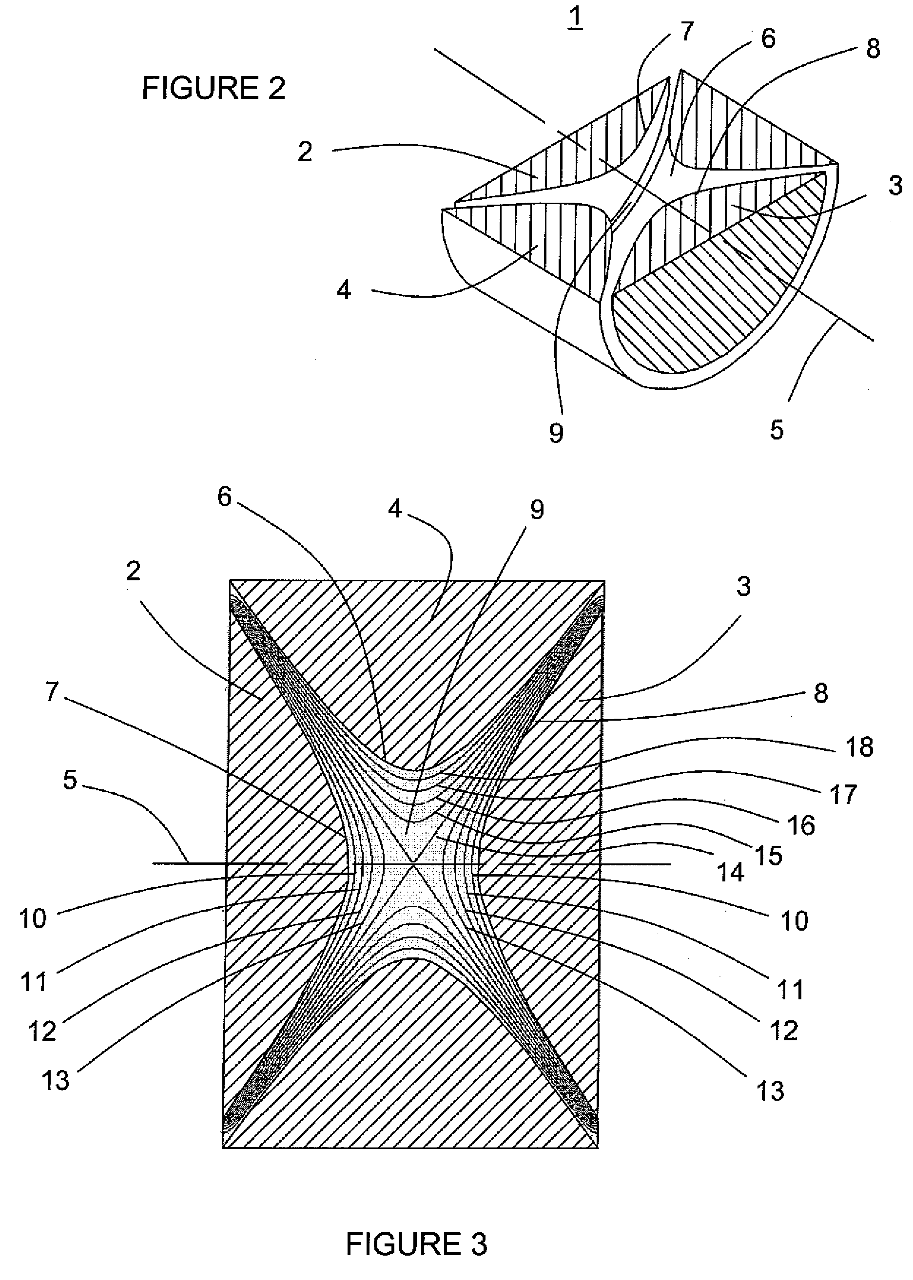
[0044]Except for a few idealized configurations, determining a solution of Laplace's equation Eq. (1) analytically is generally difficult or impossible, and the determination of an approximate solution is typically pursued via numerical methods such as FD methods. On the other hand, a problem that does have a well-known analytical solution provides a convenient approach for demonstrating the advantages and benefits provided by the subject invention relative to prior art methods. To that end, the first example described herein is that of a so-called ‘three-dimensional (3D) ion trap’. Such ion traps are commonly used to trap charged particles, particularly ions, within a volume of space enclosed by the trap. Trapping ions in such ion traps allows them to subsequently be subjected to additional processes, such as fragmentation / dissociation, reactions with other trapped ions, and interrogations via optical excitation and detection methods of ions' energy levels. Oth...
example 2
3D Ion Trap with Entrance and Exit Openings in End Cap Electrodes
[0069]The above example of an ideal 3D ion trap geometry selves to demonstrate the advantages provided by the subject invention, but there is usually little motivation or benefit derived from subjecting such ideal geometries to analysis by FD methods when analytical solutions of the potential function are available. A somewhat more practical problem is that of a 3D ion trap that incorporates openings in the end cap electrodes, in order to allow the admission of, for example, ions, electrons, and / or photons into the trap, and / or to provide an opening through which particles may exit the trap. The openings in the end cap electrodes represent deviations of the end cap electrode surface contours from the ideal. Hence, such openings result in distortions of the electric potential distribution within the trap, which are generally difficult or impossible to evaluate analytically. Consequently, numerical methods, such as Finit...
example 3
3D Ion Trap with Openings in End Cap Electrodes and Ring Electrode
[0083]The difficulties and limitations of prior art FD methods, as described above, become even more constraining for electrode geometries that do not exhibit cylindrical, i.e., rotational, symmetry. In the above two examples, the geometries exhibit cylindrical symmetry, which means that the entire three-dimensional problem need only be specified in the two-dimensional plane comprising the cross-section plane of the geometry through the axis of cylindrical symmetry. This is the plane illustrated, for example, as the plane of FIG. 10 for the 3D ion trap of example 2 above. However, many geometries do not exhibit cylindrical symmetry, in which case, the geometry needs to be defined, and the potential distribution needs to be calculated, in all three orthogonal axes, that is, in tee dimensions. In such cases, the constraints associated with limited computer memory capacity and program array sizes become substantially mor...
PUM
 Abstract
Description
Claims
Application Information