
Transition metal-containing catalysts and processes for their preparation and use as fuel cell catalysts

Inactive Publication Date: 2009-05-21
MONSANTO TECH LLC
View PDF76 Cites 63 Cited by
  • Summary
  • Abstract
  • Description
  • Claims
  • Application Information

AI Technical Summary

Benefits of technology

[0377]In a broad sense, the oxidation reaction may be practiced in accordance with the present invention at a wide range of temperatures, and at pressures ranging from sub-atmospheric to super-atmospheric. Use of mild conditions (e.g., room temperature and atmospheric pressure) have obvious commercial advantages in that less expensive equipment may be used. However, operating at higher temperatures and super-atmospheric pressures, while increasing capital requirements, tends to improve phase transfer between the liquid and gas phase and increase the PMIDA oxidation reaction rate.

Problems solved by technology

However, investigations to develop alternative catalysts have been undertaken in view of the high cost of the precious metal and other issues associated with these catalysts.
For example, while costly noble metal can often be recovered from used catalyst, the recovery process adds to the cost of processes utilizing fuel cells that include noble metal-containing catalysts.
Also, performance of cells including noble metal catalysts at the anode and / or cathode has been observed to be negatively impacted by poisoning of the anode and / or cathode by components of the fuel introduced to the cell.
But non-noble metal catalysts have not become widely-accepted alternatives to noble metal-containing fuel cell catalysts.
While many of these catalysts have been shown to be effective as cathode and / or anode catalysts and provide one or more advantages (e.g., reduced material cost), they typically suffer from one or more disadvantages.
For example, as with noble metal-containing catalysts, these catalysts often suffer from poisoning by a component of the fuel and / or typically do not provide sufficient catalytic activity for extended periods that is desired for use in economically viable fuel cells.
Thus, there has been an unfulfilled need for active non-noble metal fuel cell catalyst that may provide satisfactory performance at reasonable cost.

Method used


Image

  • Transition metal-containing catalysts and processes for their preparation and use as fuel cell catalysts
  • Transition metal-containing catalysts and processes for their preparation and use as fuel cell catalysts
  • Transition metal-containing catalysts and processes for their preparation and use as fuel cell catalysts

Examples


example 1

[0397]This example details the preparation of a precursor for use in preparing carbon-supported molybdenum carbides and nitrides.

[0398]A carbon support (20.0 g) having a B.E.T. surface area of 1067 m2 / g commercially available from Degussa Corp. was added to a 1 liter beaker containing deionized water (300 ml) and a magnetic stirring bar to form a carbon support slurry.

[0399]A solution (60 ml) of ammonium molybdate ((NH4)2MoO4) (4.236 g) (Aldrich Chemical Co., Milwaukee, Wis.) in deionized water was added to the carbon support slurry using a MasterFlex® meter pump (MasterFlex® L / S®) manufactured by Cole-Parmer Instrument Company (Vernon Hills, Ill.) at a rate of 2.0 ml / min over the course of about 30-40 minutes. The carbon support slurry was agitated using a mechanical stirrer while the molybdenum solution was added to the carbon support slurry. Also, during addition of the molybdenum solution to the carbon slurry, the pH of the resulting mixture was maintained at approximately 4.0 b...

example 2

[0402]This example details preparation of a carbon-supported molybdenum carbide catalyst using a catalyst precursor prepared as described in Example 1.

[0403]The precursor (8.0 g) was charged into a Hastelloy C tube reactor packed with high temperature insulation material. The reactor was purged by introducing argon to the reactor at approximately 100 cm3 / min and approximately 20° C. for approximately 15 minutes. A thermocouple was inserted into the center of the reactor for charging of the precursor.

[0404]After the precursor was introduced to the reactor, the temperature of the reactor atmosphere was increased to approximately 300° C. over the course of 30 minutes during which time a 50% / 50% (v / v) mixture of methane and hydrogen (Airgas Co., St. Louis, Mo.) was introduced to the reactor at a rate of about 100 cm3 / min.

[0405]The temperature of the reactor atmosphere was increased to approximately 650° C. at a rate of approximately 2° C. / min; the reactor atmosphere was maintained at ap...

example 3

[0407]This example details preparation of a carbon-supported molybdenum nitride catalyst using a catalyst precursor prepared as described in Example 1.

[0408]The precursor (10.0 g) was charged into a Hastelloy C tube reactor packed with high temperature insulation material. The reactor was purged by introducing argon to the reactor at approximately 100 cm3 / min and approximately 20° C. for approximately 15 minutes. A thermocouple was inserted into the center of the reactor for charging of the precursor.

[0409]The temperature of the reactor was then raised to about 300° C. over the course of 30 minutes during which time ammonia (Airgas Co., St. Louis, Mo.) was introduced to the reactor at a rate of about 100 cm3 / min.

[0410]After the precursor was introduced to the reactor, the temperature of the reactor atmosphere was increased to approximately 800° C. at a rate of approximately 2° C. / min. The reactor atmosphere was maintained at approximately 800° C. for approximately 4 hours. During th...


PUM


Abstract

This invention relates to the field of fuel cell catalysts, and more particularly to fuel cell catalysts including carbon supports having compositions which comprise one or more transition metals in combination with nitrogen (e.g., a transition metal nitride) formed on or over the surface of a carbon support. The present invention also relates to methods for preparation of fuel cell catalysts. The present invention further relates to the use of fuel cell catalysts described herein in processes for the generation of electric power.

Description

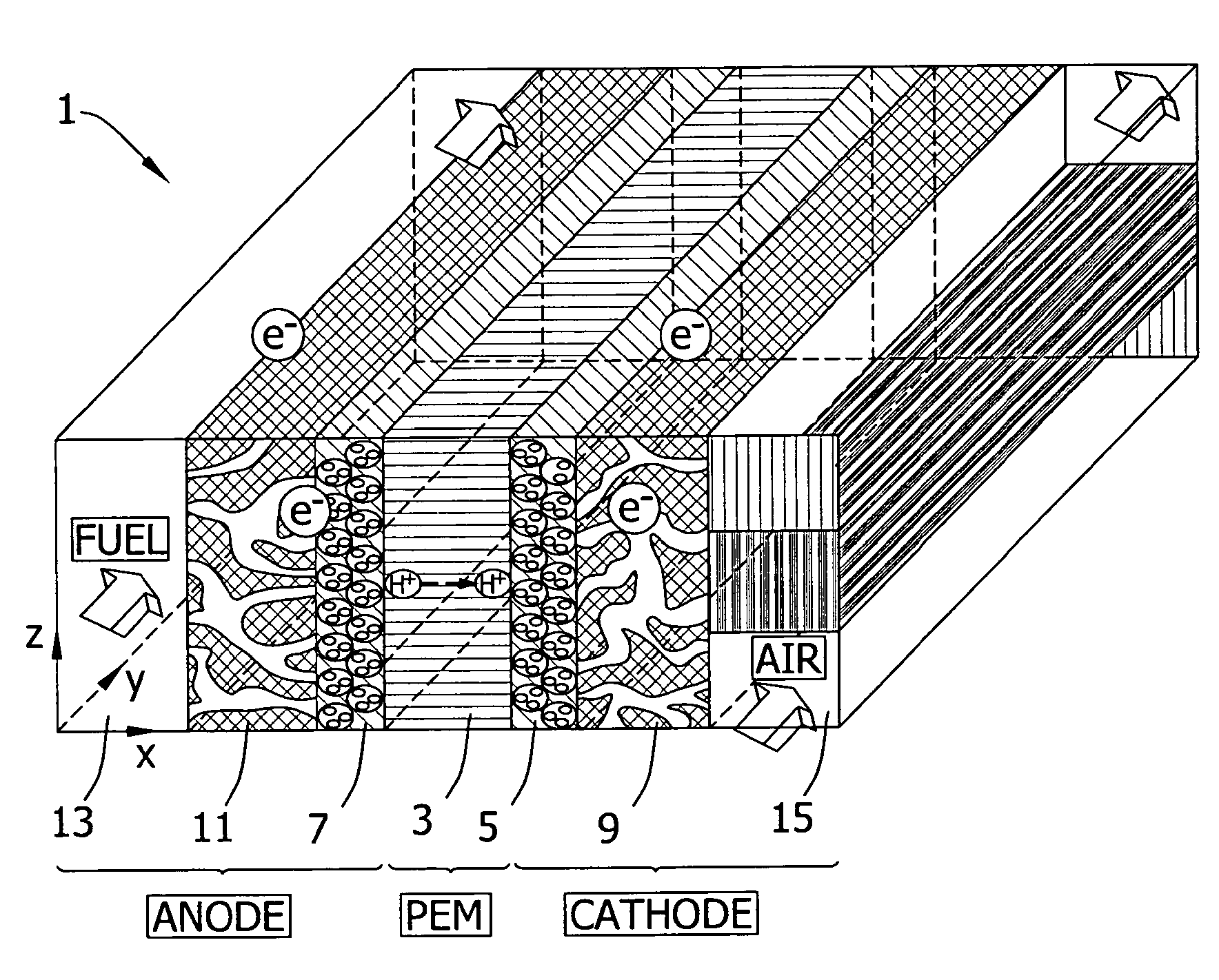
FIELD OF THE INVENTION[0001]This invention relates to the field of fuel cell catalysts, and more particularly to fuel cell catalysts including carbon supports having compositions which comprise one or more transition metals in combination with nitrogen (e.g., a transition metal nitride) formed on or over the surface of a carbon support. The present invention also relates to methods for preparation of fuel cell catalysts. The present invention further relates to the use of fuel cell catalysts described herein in processes for the generation of electric power.BACKGROUND OF THE INVENTION[0002]Fuel cells are electrochemical devices that convert the chemical energy of a fuel directly into electrical energy. Fuel cells are generally known to be clean and highly efficient means for generation of energy. Advantageously, fuel cells typically use readily available materials (e.g., methanol or hydrogen) as fuel. A fuel cell generally includes an anode, a cathode, a medium separating the anode ...

Claims


Application Information

Patent Timeline
IPC IPC(8): H01M8/04H01M4/90H01M8/10
CPCH01M4/9008H01M4/9016H01M4/9083Y02E60/50H01M4/926H01M2008/1095Y02E60/523H01M4/923
Inventor LIU, FUCHENARHANCET, JUAN P.MENCH, MATTHEW M.
Owner MONSANTO TECH LLC
Learn More