Imaging reader for and method of improving visibility of aiming pattern

a technology of aiming pattern and image reader, which is applied in the field of image reader for and method of improving visibility of aiming pattern, can solve the problems of slowing down transaction processing and reducing productivity, difficult to overcome blind aiming at the symbol, and difficult use of imaging reader for reading symbols, etc., to prevent image blurring and short exposure time

Active Publication Date: 2009-04-02
SYMBOL TECH LLC
View PDF10 Cites 13 Cited by
  • Summary
  • Abstract
  • Description
  • Claims
  • Application Information

AI Technical Summary

Benefits of technology

[0008]A one- or two-dimensional, solid-state imager under control of a controller is mounted in the reader, and includes an array of image sensors operative for capturing light from a one-dimensional and / or a two-dimensional symbol over a field of view, and for generating an electrical signal indicative of the captured light. The field of view of the imager diverges in an outward direction away from the imager. Preferably, the array is a charge coupled device (CCD) or a complementary metal oxide semiconductor (CMOS) array. An imaging lens is preferably mounted in the reader in front of the imager to focus the captured light onto the imager. The imaging lens causes the field of view to rapidly widen at a steeper angle of divergence.
[0009]The imager may be associated with a high-speed strobe illuminator under control of the controller to enable the image of the symbol to be acquired in a very short period of time, for example, on the order of 500 microseconds, so that the symbol image is not blurred even if there is relative motion between the imager and the symbol. The strobe illumination is preferably brighter than ambient illumination. The illumination can also be continuous. The imager captures light over an exposure time period, also under the control of the controller. A short exposure time also prevents image blurring. The controller is also operative for processing the electrical signal into data indicative of the symbol being read.
[0011]In a preferred embodiment, the controller is operative for determining an ambient light condition above a threshold light intensity, and for modulating the aiming light pattern only when the ambient light condition determined by the controller is above the threshold light intensity. The threshold light intensity is the level of ambient light below which the aiming light pattern becomes difficult to visually discern. Thus, the aiming light pattern is preferably not modulated under low ambient light where there is less of a necessity to make the aiming light pattern more noticeable. Alternatively, rather than not modulating the aiming light pattern under low ambient light conditions, the aiming light pattern can be modulated at a high blink frequency, e.g., above 25 Hertz, and at a low duty cycle, such that the operator will not notice any change in the intensity of the aiming light pattern due to the integration of the human eye. This is especially useful for some operators who may find the modulated aiming light pattern objectionable. One way to determine a brightly lit environment is to have the controller determine a gain of the imager over a time period.
[0012]The aiming light assembly preferably includes one or a plurality of light sources and one or a plurality of pattern shaping optical elements, such as diffractive or refractive optical elements. One or each light source is advantageously a laser. In order to modulate the aiming light pattern, the controller pulses one or each laser in a blinking mode at a duty cycle, for example, on the order of 50 percent. This allows the output power of one or each laser to be increased for each pulse, thereby increasing the brightness of the aiming light pattern, but the average output power is kept below safety restriction levels due to the duty cycle. In addition, the working lifetime of each laser is increased due to the duty cycle.

Problems solved by technology

Yet, the use of imaging readers, especially hand-held movable readers, for reading symbols has proven to be challenging.
It is not uncommon for the operator to repeatedly move the portable reader in multiple directions and repeatedly aim the portable reader at a single symbol several times before an indicator advises the operator that the symbol has been successfully read, thereby slowing down transaction processing and reducing productivity.
However, in most cases, this blind aiming at the symbol is difficult to overcome, especially when the position and orientation of the symbol are variable.
As advantageous as such aiming light arrangements are, they have proven to be less than satisfactory in certain situations.
For example, in a brightly lit environment illuminated by indoor lighting of high intensity, or by outdoor lighting such as sunlight, it is often difficult for the operator to see the aiming pattern, because the aiming pattern is “drowned” out by the bright ambient light.
However, it is not always possible to increase the laser beam output power enough to have an aiming light pattern that is easily visibly discernible by the operator, especially in a brightly lit environment, due to laser safety restrictions.

Method used


Image

  • Imaging reader for and method of improving visibility of aiming pattern
  • Imaging reader for and method of improving visibility of aiming pattern
  • Imaging reader for and method of improving visibility of aiming pattern

Examples


Embodiment Construction

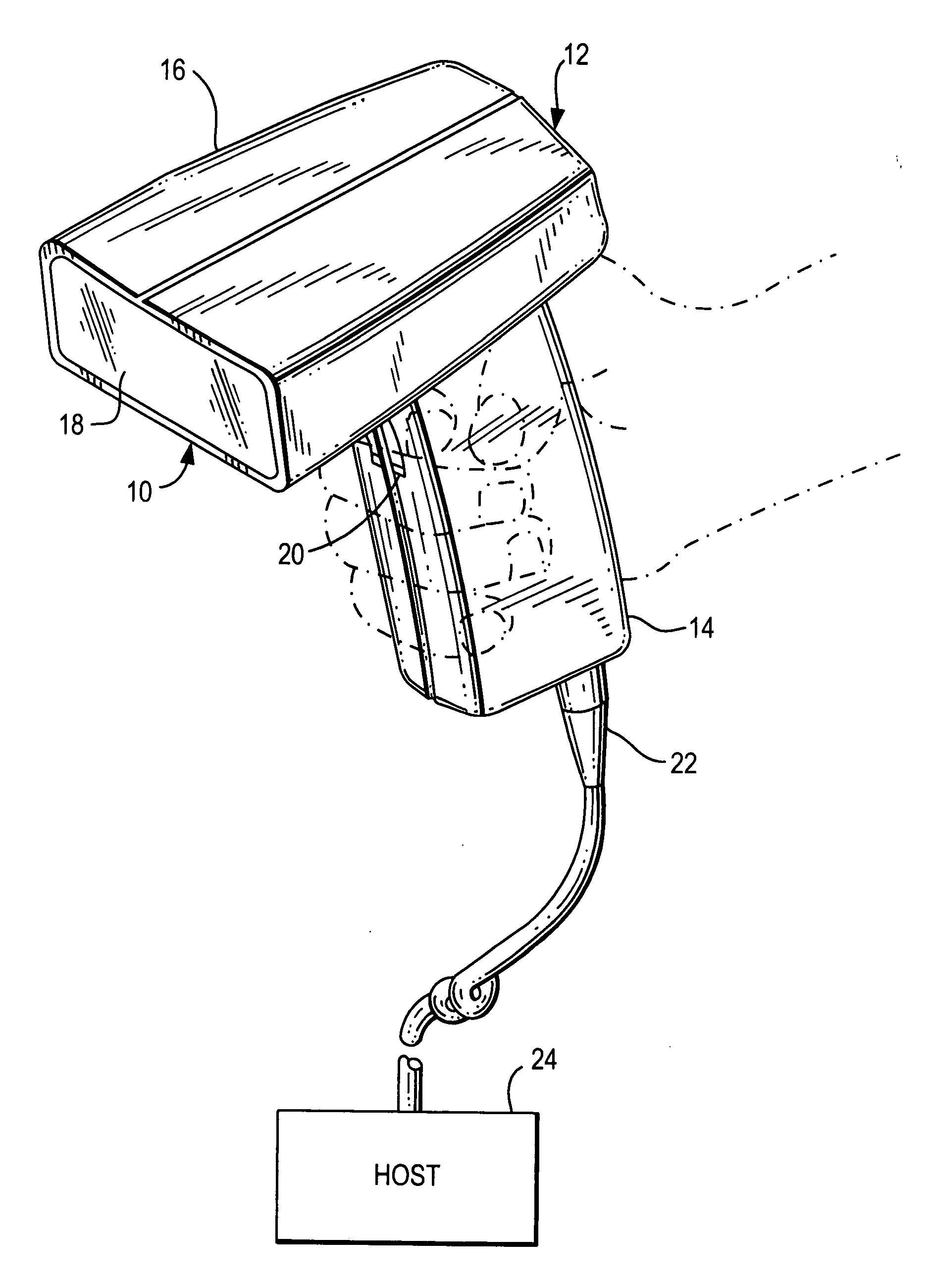
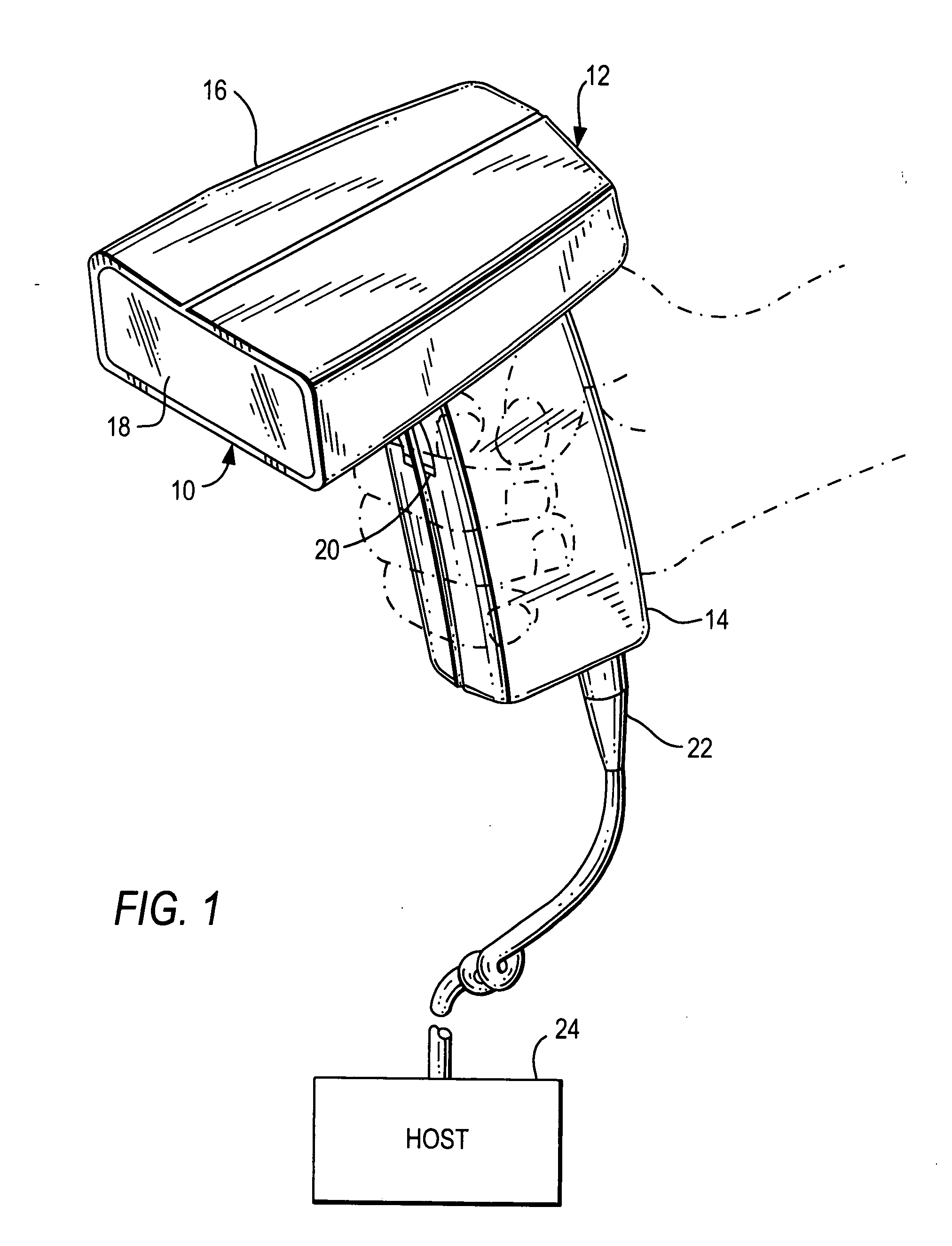
[0018]Reference numeral 10 in FIG. 1 generally identifies a hand-held imaging reader for electro-optically reading symbols or like indicia on products or like targets. The reader 10 includes a housing 12 in which an aiming light assembly, as described in detail below in accordance with this invention, is incorporated. The housing 12 includes a generally elongated handle or lower handgrip portion 14 and a barrel or upper body portion 16 having a front end at which a light-transmissive window 18 is located. The cross-sectional dimensions and overall size of the handle are such that the reader can conveniently be held in an operator's hand.

[0019]The body and handle portions may be constructed of a lightweight, resilient, shock-resistant, self-supporting material such as a synthetic plastic material. The plastic housing may be injection molded, but can be vacuum-formed or blow-molded to form a thin hollow shell which bounds an interior space whose volume is sufficient to contain the var...


PUM


Abstract

An aiming light assembly supported by a mobile imaging reader projects an aiming light pattern on a symbol. A controller modulates the aiming light pattern to render the aiming light pattern more visibly discernible to an operator, especially in a brightly lit ambient environment, to enable the operator to position the aiming light pattern on the symbol prior to reading.

Description

BACKGROUND OF THE INVENTION[0001]Solid-state imaging readers have been used in supermarkets, warehouse clubs, department stores, and other kinds of retailers to electro-optically read one-dimensional bar code symbols, particularly of the Universal Product Code (UPC) type, on products to be purchased, each symbol having a row of bars and spaces spaced apart along one direction, and also for processing two-dimensional symbols, such as Code 49, on such products, as well as other items. The structure of Code 49, which introduced the concept of vertically stacking a plurality of rows of bar and space patterns in a single symbol, is described in U.S. Pat. No. 4,794,239. Another two-dimensional code structure for increasing the amount of data that can be represented or stored on a given amount of surface area is known as PDF417 and is described in U.S. Pat. No. 5,304,786.[0002]A typical imaging reader has a one- or two-dimensional array of cells or photosensors, which correspond to image e...

Claims


Application Information

Patent Timeline
Patent Type & Authority Applications(United States)
IPC IPC(8): G06K7/10G06K9/22
CPCG06K2207/1011G06K7/14
Inventor VINOGRADOV, IGORTRAJKOVIC, MIROSLAV
Owner SYMBOL TECH LLC
Why Eureka
Try Eureka