Servo valve

a technology of servo valves and valve bodies, which is applied in the direction of valve operating means/releasing devices, mechanical equipment, transportation and packaging, etc., can solve the problem of excessive rise in the return flow pressure, and achieve the effect of excessive return flow pressur

Inactive Publication Date: 2009-04-02
TRW AUTOMOTIVE GMBH
View PDF4 Cites 0 Cited by
  • Summary
  • Abstract
  • Description
  • Claims
  • Application Information

AI Technical Summary

Benefits of technology

[0007]In accordance with the invention, a servo valve for a hydraulic power steering system includes a valve shaft that is rotatable about a valve axis, a valve sleeve that cooperates with and may be rotated in relation to the valve shaft, and a closure member for a valve return port. The closure member is movable between a first end position, in which it closes a flow cross-section of the valve return port at least partially, and a second end position, in which it substantially clears the flow cross-section of the valve return port. The closure member is urged towards one of the end positions by a supply pressure applied on a valve supply port by a hydraulic fluid. Since in this case the movement of the closure member depends on the hydraulic pressure at the valve supply port, rather than directly on the rotation of the valve shaft in relation to the valve sleeve, a reaction of the closure member on a center positioning action of the servo valve is ruled out. The force for returning to the center position may therefore be adjusted by means of a centering apparatus without any undesirable influence by the closure member. In addition, an increase in the return flow pressure results in an improved damping response of the power steering system, which has an advantageous effect on the hydraulic stability of the steering gear.
[0008]In one embodiment the closure member includes a throttle opening which defines a minimum flow cross-section of the valve return port. The throttle opening prevents the valve return port from being completely closed and, hence, an excessive rise in the return flow pressure.
[0009]Preferably, the supply pressure urges the closure member towards its first end position. This means that as the supply pressure rises and as an attendant risk of cavitation in the servo valve increases, the closure member is urged more strongly into that end position in which the closure member at least partly closes the flow cross-section of the valve return port. A reduction in the flow cross-section will result in an increase of the return flow pressure, which counteracts the increasing risk of cavitation and largely prevents any cavitation phenomena from appearing.

Problems solved by technology

The throttle opening prevents the valve return port from being completely closed and, hence, an excessive rise in the return flow pressure.

Method used


Image

  • Servo valve
  • Servo valve
  • Servo valve

Examples


Embodiment Construction

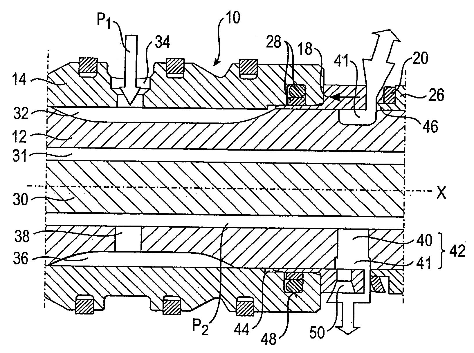
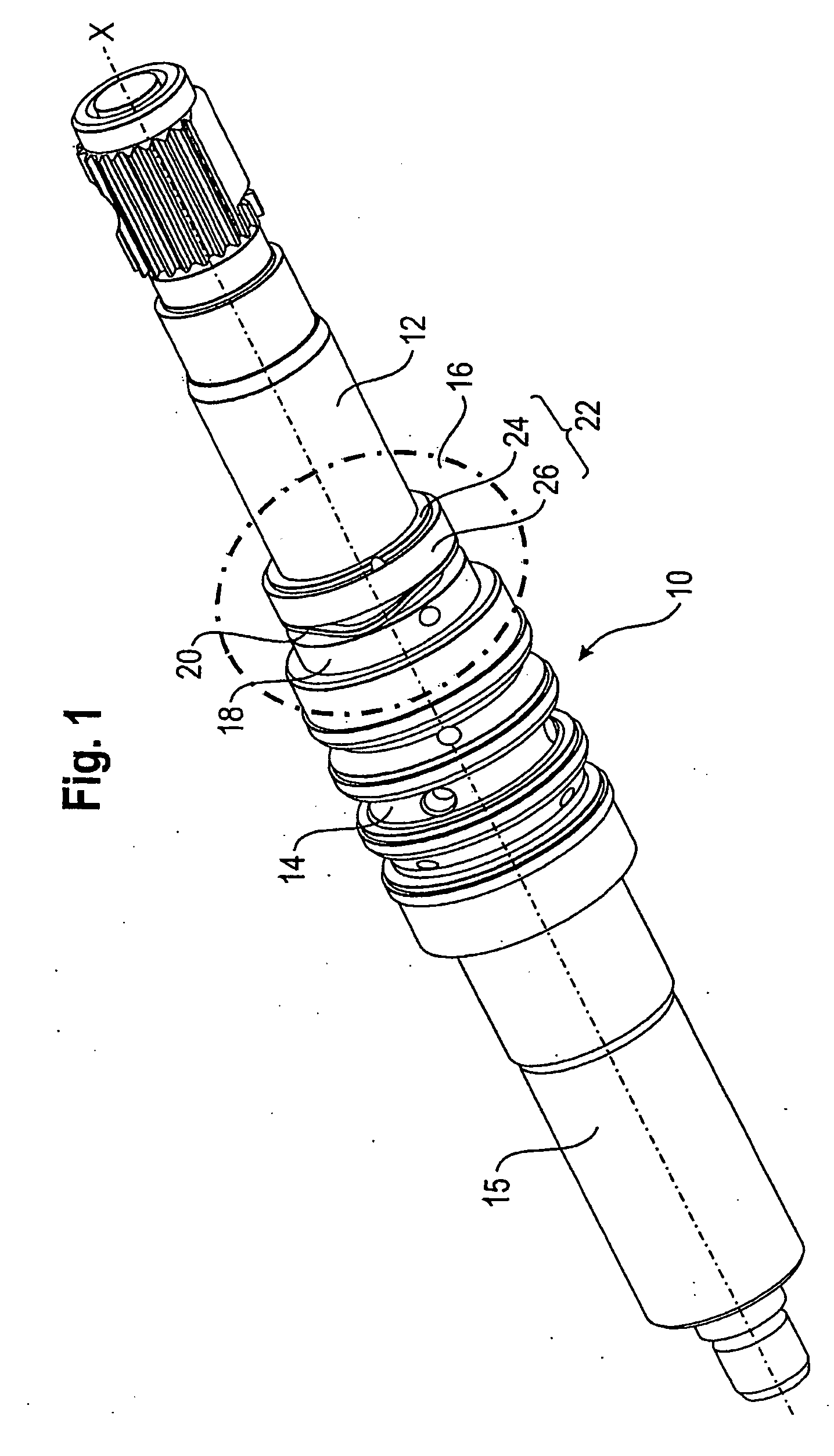
[0029]FIG. 1 shows a servo valve 10 having a valve shaft 12 and a valve sleeve 14 that cooperates with the valve shaft 12. The valve shaft 12 is coupled to a steering wheel (not shown) for joint rotation therewith about a valve axis X, while the valve sleeve 14 is connected to a steering gear, for example to an output shaft 15, provided with a pinion, of the steering gear and may be rotated in relation to the valve shaft 12. The servo valve 10 discussed here is a hydraulic servo valve the basic structure of which is known from the prior art, for example from U.S. Pat. No. 4,819,545. This document is expressly incorporated herein in its entirety by reference.

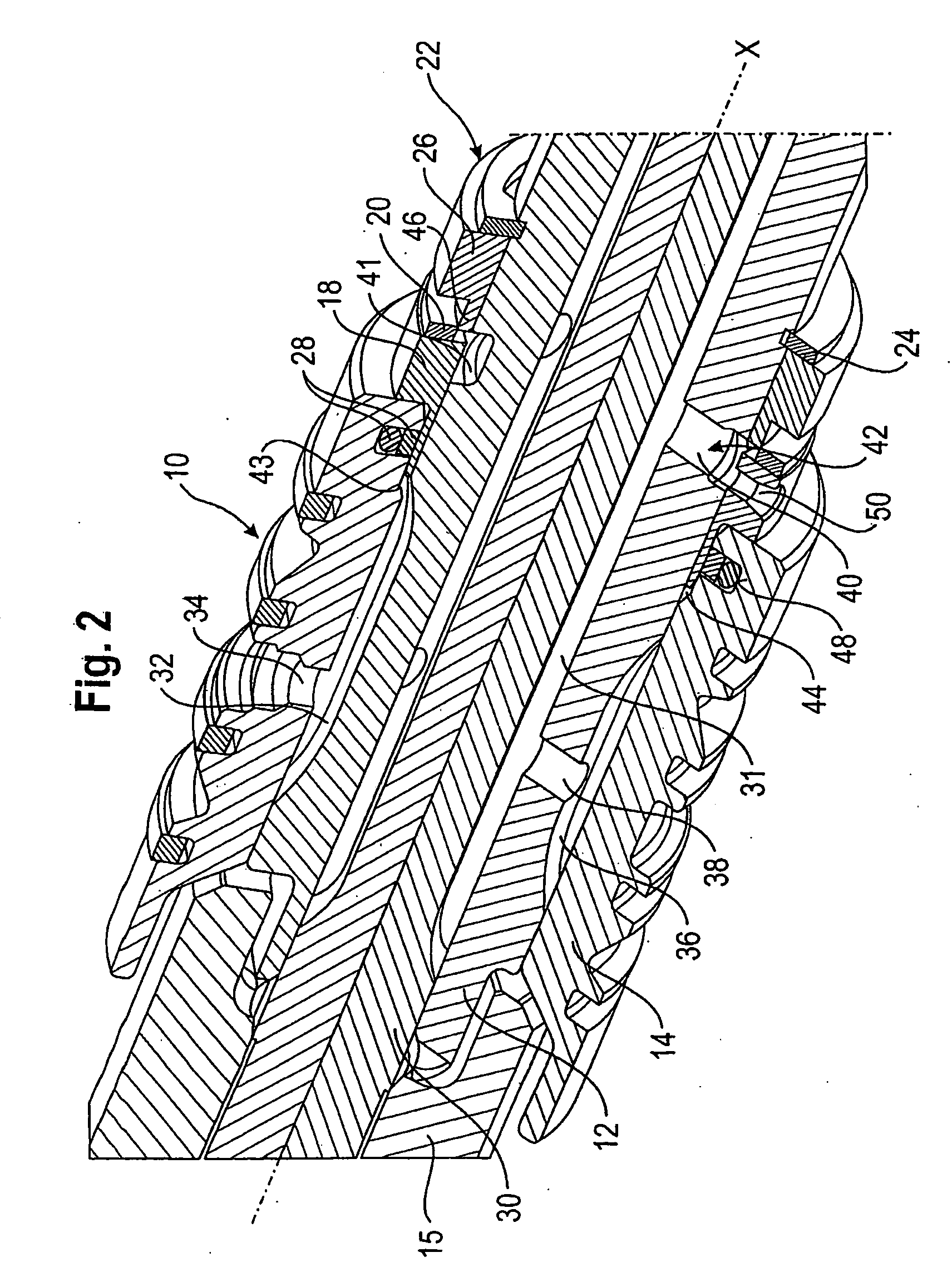
[0030]The special characteristic of the servo valve 10 is an assembly 16 which is highlighted in FIG. 1 (cf. dash-dot framing) and which, depending on a supply pressure P1 of the servo valve 10, adjusts a flow cross-section of a valve return port and thus a return flow pressure P2 (cf. FIGS. 3 and 4). The assembly 16 comprises a ...


PUM


Abstract

A servo valve for a hydraulic power steering system includes a valve shaft that is rotatable about a valve axis, a valve sleeve that cooperates with and may be rotated in relation to the valve shaft, and a closure member for a valve return port. The closure member is movable between a first end position, in which it closes a flow cross-section of the valve return port at least partially, and a second end position, in which it substantially clears the flow cross-section of the valve return port. The closure member is urged towards one of the end positions by the supply pressure applied on a valve supply port by a hydraulic fluid.

Description

CROSS-REFERENCE TO RELATED APPLICATION[0001]This application claims priority to German Patent Application No. 20 2007 013 585.8 filed Sep. 28, 2007, the disclosures of which are incorporated herein by reference in entirety.BACKGROUND OF THE INVENTION[0002]The present invention relates to a servo valve for a hydraulic power steering system, including a valve shaft that is rotatable about a valve axis, and a valve sleeve that cooperates with and may be rotated in relation to the valve shaft.[0003]A servo valve is a central constituent of a hydraulic power steering system which is able to provide a steering assist force to the driver of a vehicle. One example of such a power steering system is found in U.S. Pat. No. 4,819,545. Here, the valve shaft connected to a steering wheel and the valve sleeve connected to a steering gear are each provided with control grooves for controlling a hydraulic fluid flow through the servo valve. In an initial condition, in which the valve shaft and the ...

Claims


Application Information

Patent Timeline
IPC IPC(8): F16K31/12
CPCB62D5/083
Inventor LINGEMANN, MARKUS
Owner TRW AUTOMOTIVE GMBH
Why Eureka
Try Eureka