Planar light source and method of manufacturing planar light source

Inactive Publication Date: 2009-04-02
CITIZEN ELECTRONICS CO LTD
View PDF14 Cites 23 Cited by
  • Summary
  • Abstract
  • Description
  • Claims
  • Application Information

AI Technical Summary

Benefits of technology

[0013]The present invention has been made in view of the above-described problems with the conventional planar light sources. Accordingly, an object of the present invention is to provide a planar light source that is le

Problems solved by technology

However, the lightguide plate used in this planar light source is large in size, which hinders reduction in size and thickness of the display apparatus.
In addition, it is difficult for the whole light-emitting surface to have a uniform luminance distribution.
The above-described conventional plan

Method used


Image

  • Planar light source and method of manufacturing planar light source
  • Planar light source and method of manufacturing planar light source
  • Planar light source and method of manufacturing planar light source

Examples


first embodiment

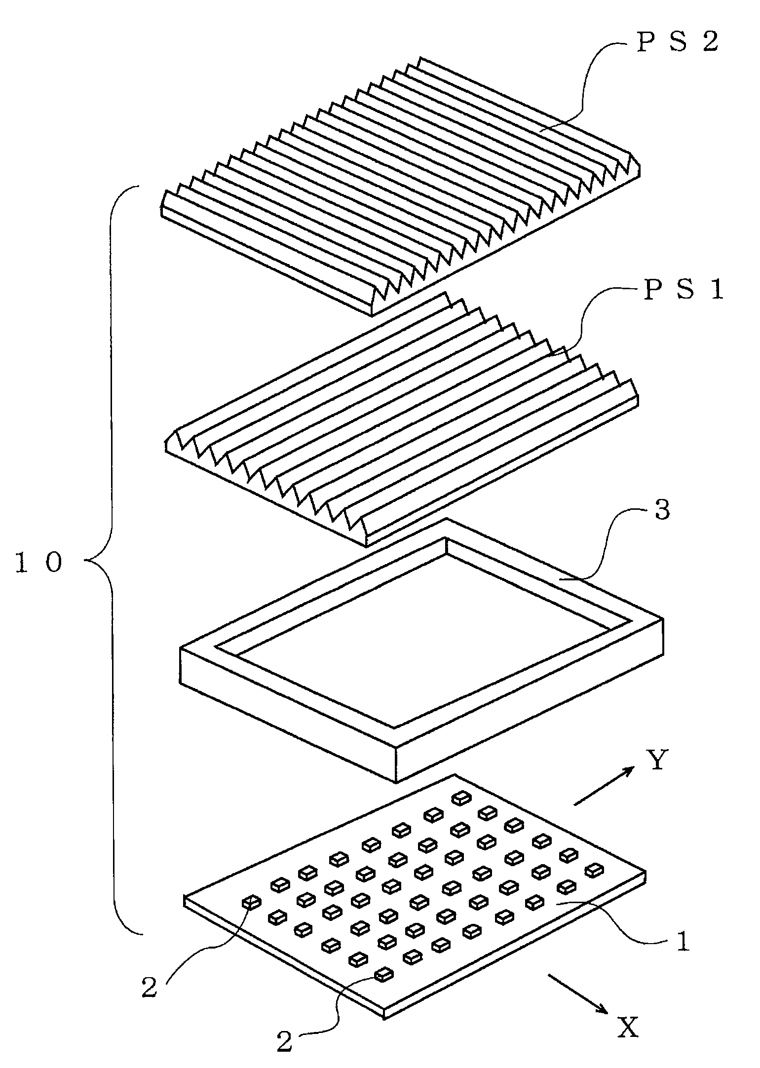
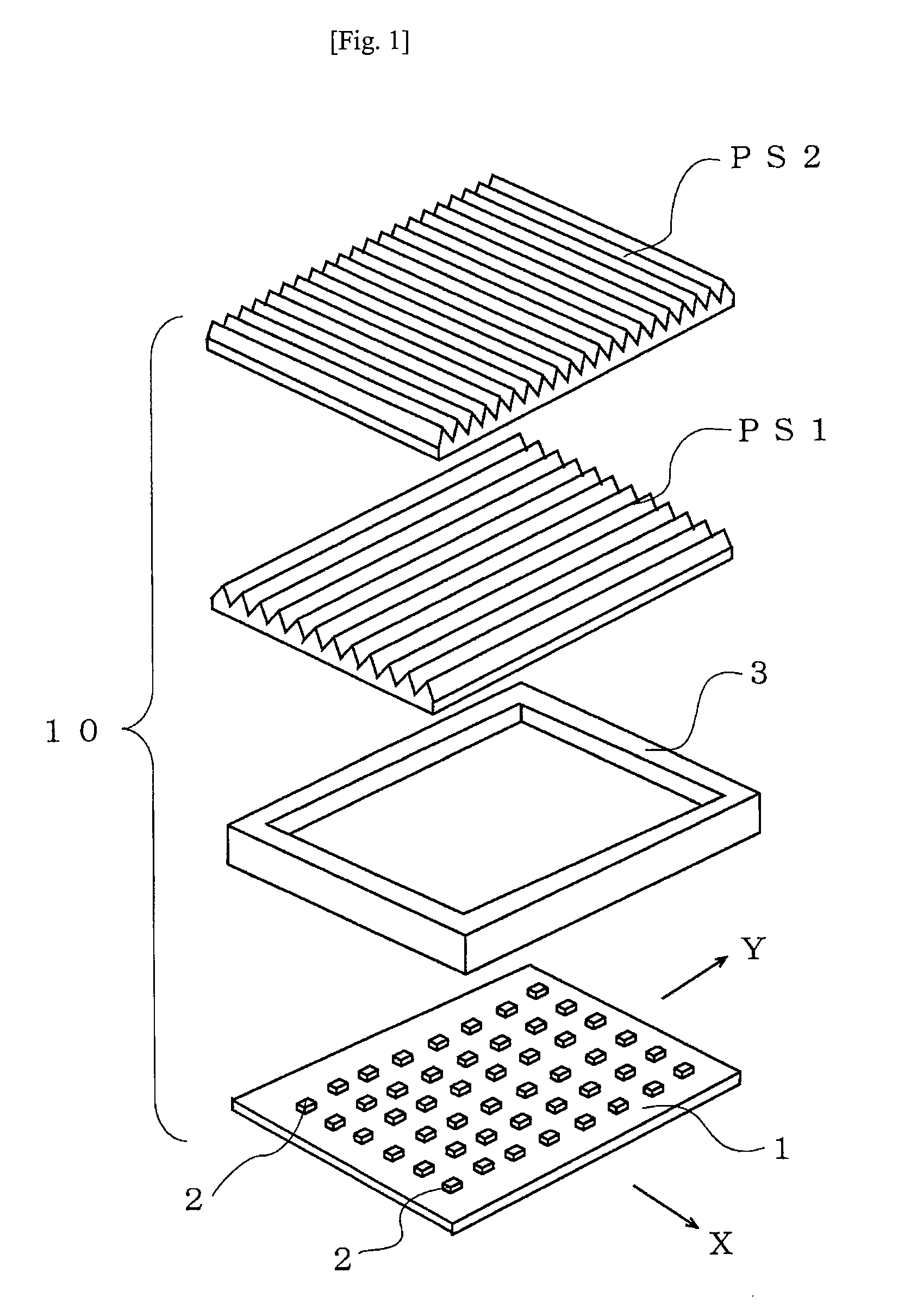
[0046]A planar light source 10 according to the present invention has, as shown in FIGS. 1 to 5, a light source substrate 1 having a plurality of LEDs 2 arranged in a matrix. The planar light source 10 further has two prism sheets PS1 and PS2 disposed over the light source substrate 1 with a frame 3 interposed between the prism sheet PSI and the light source substrate 1. The prism sheets PS1 and PS2 each have a plurality of prisms provided on their top surfaces and are disposed with their respective prisms perpendicularly intersecting each other in plan view.

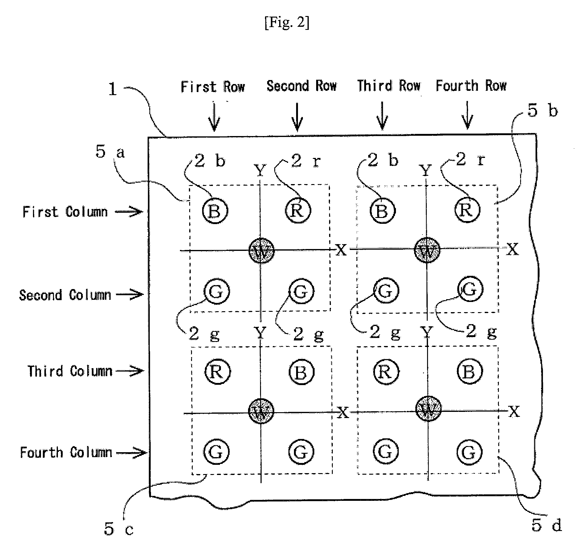
[0047]FIG. 2 is a fragmentary enlarged plan view of a part of the light source substrate 1. In the X-Y coordinate system of the light source substrate 1, B LEDs 2b and R LEDs 2r are alternately disposed in a first column parallel to the X axis at substantially equal intervals. In a second column, only G LEDs 2g are disposed at substantially equal intervals. In a third column, R LEDs 2r and B LEDs 2b are alternately disposed at s...

second embodiment

[0072]Next, a light source substrate in the present invention will be explained with reference to FIG. 12. FIG. 12 is a fragmentary enlarged plan view of a part of a light source substrate 11, showing light sources R, G and B LEDs arranged in a matrix in the same way as the light source substrate 1 shown in FIG. 2. The light source substrate 11 differs from the light source substrate 1 shown in FIG. 2 in the arrangement of R, G and B LEDs. That is, on the light source substrate 11, G LEDs 2g and R LEDs 2r are alternately disposed in a first column parallel to the X axis at substantially equal intervals. In a second column, B LEDs 2b and G LEDs 2g are alternately disposed at substantially equal intervals. In a third column, G LEDs 2g and R LEDs 2r are alternately disposed at substantially equal intervals. In a fourth column, B LEDs 2b and G LEDs 2g are alternately disposed at substantially equal intervals.

[0073]In other words, in odd-numbered columns, G and R LEDs 2g and 2r are alter...


PUM


Abstract

A planar light source directly mixes three colors of light from light-emitting diodes into white light. The planar light source has a plurality of red (2r), green (2g) and blue (2b) light-emitting diodes mounted on a mount surface of a substrate to define a plurality of light source sets, each having mutually adjacent red, green and blue light-emitting diodes, and further has first and second prism sheets (PS1 and PS2) stacked to face the mount surface. The stacked prism sheets receive and mix three colors of light from the light-emitting diodes constituting each light source set and emit lights from the red, green and blue light-emitting diodes of each of the light source sets as white light.

Description

RELATED APPLICATIONS[0001]This application claims priority under 35 U.S.C. §119 to Japanese Patent application No. JP2007-255252 filed on Sep. 28, 2007, the entire content of which is hereby incorporated by reference.TECHNICAL FIELD[0002]The present invention relates to a planar light source that mixes incident light from a plurality of light-emitting diode (LED) light sources and emits mixed light. The present invention also relates to a method of manufacturing the planar light source.RELATED ART[0003]Conventionally, a white light source is used as a backlight unit for a liquid crystal display apparatus or the like. The white light source mixes light emitted from a plurality of LED light sources to generate white light. In general, a planar light source is used as the white light source. In the planar light source, LEDs of three different colors are disposed along a side edge surface of a lightguide plate to make three colors of light, i.e. red (R), green (G), and blue (B), enter t...

Claims


Application Information

Patent Timeline
IPC IPC(8): F21V5/02
CPCG02F1/133603G02F2001/133607G02F1/133606G02F1/133607
Inventor NOBA, KOYAWATANABE, TAKASHI
Owner CITIZEN ELECTRONICS CO LTD
Why Eureka
Try Eureka