Mat member, exhaust gas treatment apparatus, and muffling apparatus
a technology of exhaust gas treatment and muffling apparatus, which is applied in the direction of machines/engines, separation processes, filtration separation, etc., can solve problems such as damage to the world-wide environment, and achieve the effect of better controlling the amount of organic components
- Summary
- Abstract
- Description
- Claims
- Application Information
AI Technical Summary
Benefits of technology
Problems solved by technology
Method used
Image
Examples
example 1
[0100]First, silica sol is added to basic aluminum chloride aqueous solution with aluminum content of 70 g / l and Al / Cl=1.8 (atom ratio) such that the relative proportion of Al2O3:SiO2 in alumina-based fibers is 72:28 to prepare the precursor of alumina-based fibers. Next, polyvinyl alcohol is added to the precursor of alumina-based fibers. Further, this liquid is condensed to prepare a spinning solution. From the spinning solution, fibers are formed by the blowing spinning process. The flow rate of the carrier gas (air) is 52 m / s and the supplying rate of the spinning solution is 5.3 ml / h.
[0101]Then, the precursor of the alumina-based fibers is folded and laminated to form a base member of alumina-based fibers.
[0102]Next, the needling process is performed to the obtained base member. In the needling process, a needling board having needles at a density of 80 needles per 100 cm2 is provided on one side of the base member and the needling is performed from the one side of the base mem...
examples 2 through 4
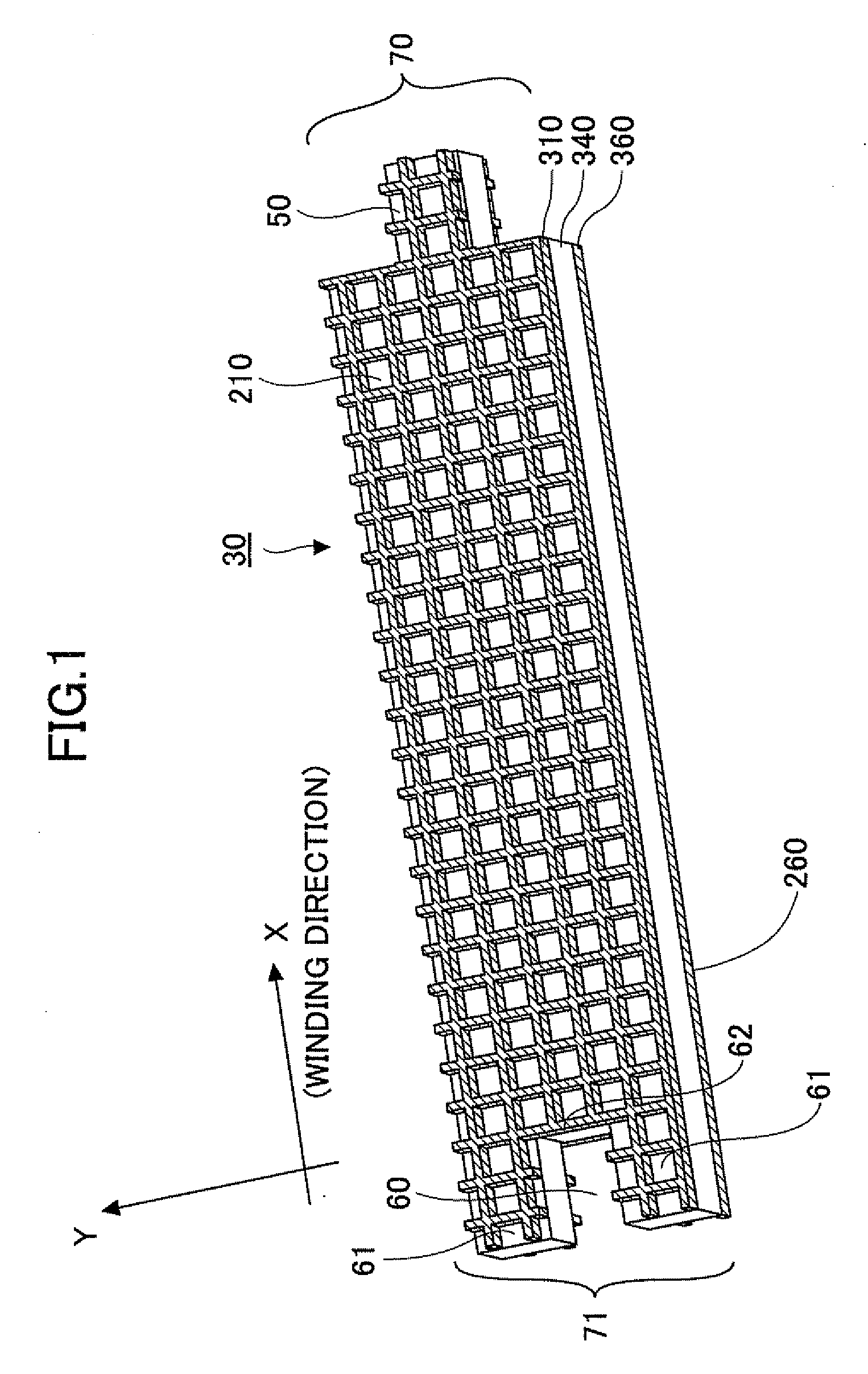
[0106]In the same manner as above, mat members “Examples 2 through 4” each having a sheet member and openings on the first main surface of the mat member are formed. However, in “Example 2”, the pitch of the straight lines constituting the framework part of the sheet member in both X1 and Y1 directions (distance between the centers of adjoining straight lines) is 4 mm; the maximum length of the openings of the sheet member is 5.7 mm; and the opening ratio is 93%. In “Example 3”, the pitch of the straight lines in both X1 and Y1 directions (distance between centers of adjoining straight lines) is 6 mm; the maximum length of the openings of the sheet member is 8.5 mm; and the opening ratio is 95%. In “Example 4”, the pitches of the straight lines (distances between the centers of adjoining straight lines) in X1 and Y1 directions are 8 mm and 9 mm, respectively; the maximum length of the openings of the sheet member is 12.0 mm; and the opening ratio is 96%.
example 5
[0107]In the same manner as in “Example 2”, a mat member (“Example 5”) is formed. However, in “Example 5” after a sheet member having openings is disposed on the first main surface of the base member, the base member is reversed so that another sheet member having openings is disposed on the entire second main surface of the base member in the same manner described above. The specifications of the sheet members disposed on both main surfaces are the same as those of the sheet member used in “Example 2”. Namely, the pitch of the straight lines constituting the framework part of the sheet member in both X1 and Y1 directions (distance between the centers of adjoining straight lines) is 4 mm; the maximum length of the openings of the sheet member is 5.7 mm; and the opening ratio is 93%.
PUM
| Property | Measurement | Unit |
|---|---|---|
| length | aaaaa | aaaaa |
| angle | aaaaa | aaaaa |
| shapes | aaaaa | aaaaa |
Abstract
Description
Claims
Application Information
 - R&D
- Intellectual Property
- Life Sciences
- Materials
- Tech Scout
- Unparalleled Data Quality
- Higher Quality Content
- 60% Fewer Hallucinations
Browse by: Latest US Patents, China's latest patents, Technical Efficacy Thesaurus, Application Domain, Technology Topic, Popular Technical Reports.
© 2025 PatSnap. All rights reserved.Legal|Privacy policy|Modern Slavery Act Transparency Statement|Sitemap|About US| Contact US: help@patsnap.com


