Gas burner capable of multilevel controlled

A gas burner and burner technology, applied in the direction of liquid fuel burner, gas fuel burner, burner, etc., can solve the problems of high product cost, difficult to manufacture, difficult fuel gas and air mixing ratio, etc., to achieve reduction The amount, easy to manufacture the effect

Inactive Publication Date: 2004-05-19
KYUNGDONG NAVIEN
View PDF0 Cites 7 Cited by
  • Summary
  • Abstract
  • Description
  • Claims
  • Application Information

AI Technical Summary

Problems solved by technology

[0033] However, when the flame temperature is lowered in conventional premixed gas burners, the burner flame may be unstable, which may result in higher product cost, and may be difficult to manufacture
Also, in household gas burner equipment with a simple structural design, it may occur that it is difficult to stably control the combustion of the premixed gas
[0034] Also, when a woven metal fiber mat of ceramic, stainless steel, or porous metal fiber fabric is used as the combustion surface material for the premixed combustion gas slot, the premixer for the premixed fuel gas and air may be larger and slightly complex
Therefore, during combustion, abnormal noise may be generated in the high load area, or the main flame of the gas burner may be unstable due to increased air flow resistance due to pressure loss in the premixer
[0035] As mentioned above, when a mixing chamber is used in a general premixed gas burner as an additional unit for mixing fuel gas and air and supplying the mixture, the structure becomes complicated and it is difficult to mix the fuel gas and air than set to an appropriate value
[0036] In particular, mixing chambers cannot be used in burners with multi-stage control

Method used


Image

  • Gas burner capable of multilevel controlled
  • Gas burner capable of multilevel controlled
  • Gas burner capable of multilevel controlled

Examples


Embodiment Construction

[0053] A gas burner capable of multi-stage control according to a preferred embodiment of the present invention will be described below with reference to the accompanying drawings.

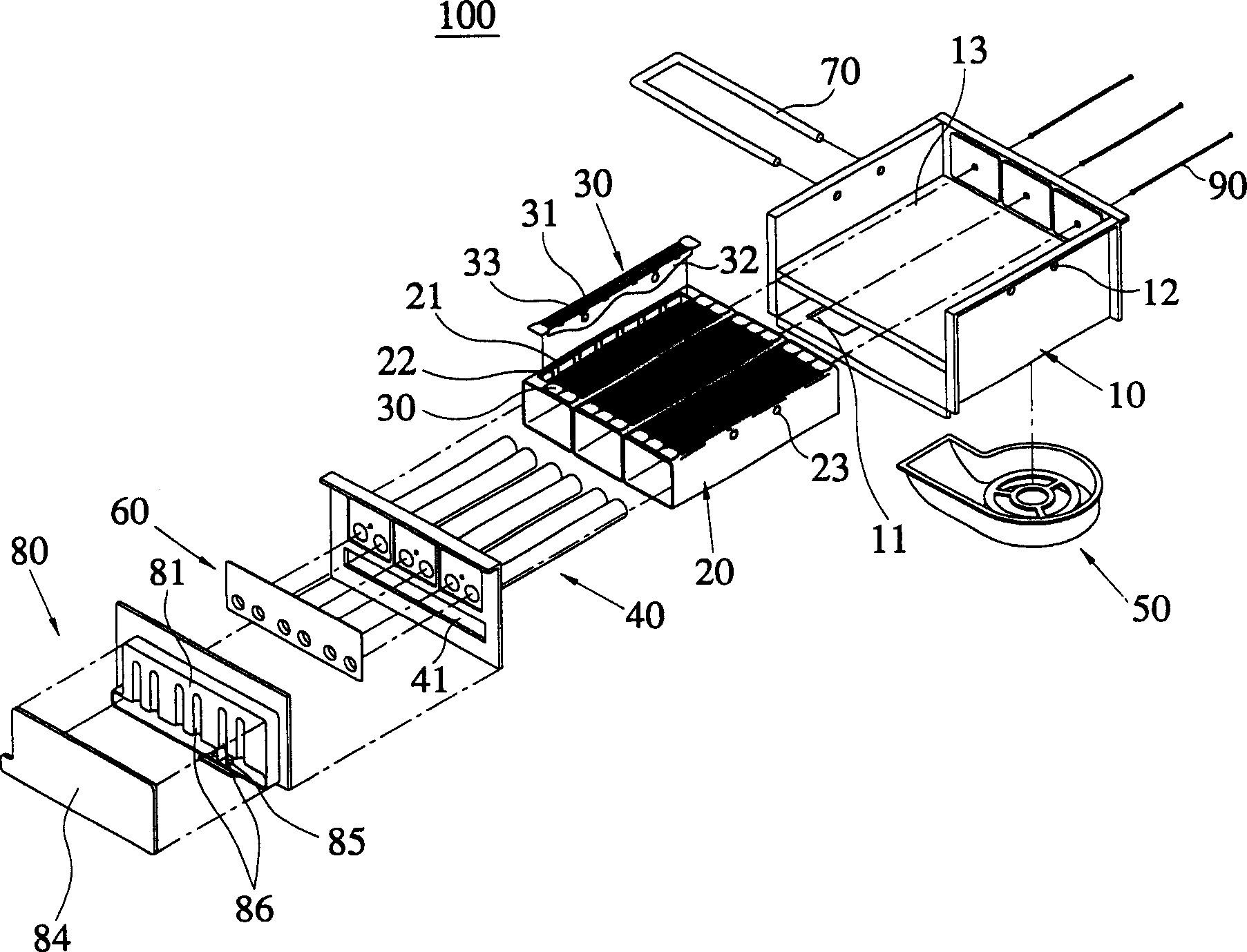
[0054] refer to Figures 3 to 10 , the gas burner capable of multi-stage control includes at least one tube burner 20 and at least one plate burner 30 each having the same burner output capacity, which are arranged in parallel to each other, wherein the number of working burners can be determined according to Desired number of calories varies.

[0055] Preferably, the multi-stage controllable gas burner 100 includes a main housing 10 , at least one tube burner 20 , at least one plate burner 30 , a plurality of mixture supply pipes 40 , a venturi 60 and a manifold 80 .

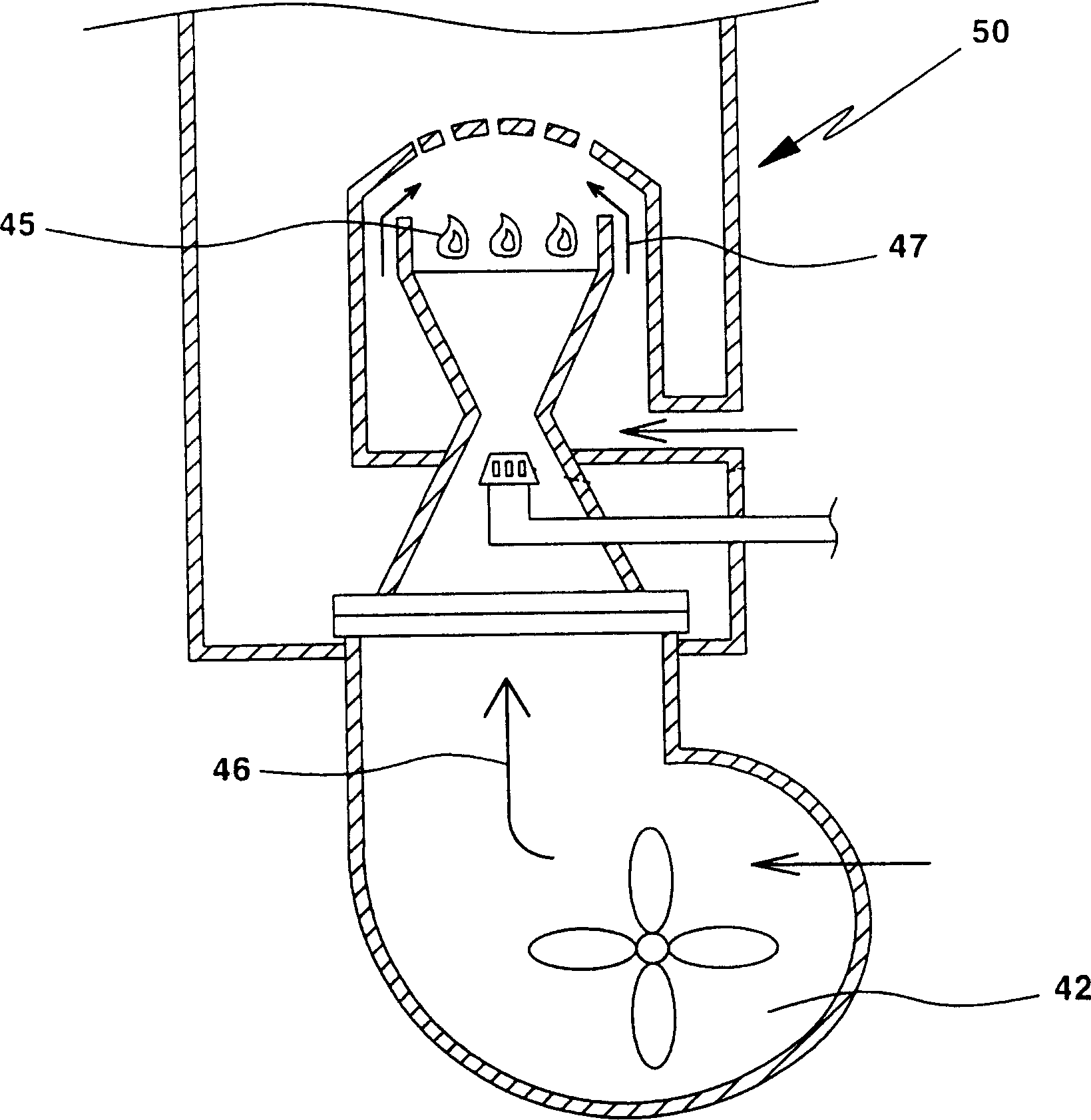
[0056] Here, the blower 50 is installed on the bottom surface of the main case 10 such that air can be supplied from the blower 50 through the air inlet 11 formed at the bottom of the main case 10 .

[0057] A tubular burner 20 i...


PUM


Abstract

A combustion gas burner enabling a multi-stage control is provided, which includes a main casing on the bottom surface of which an air blower is mounted so that air can be supplied from the air blower through an air inlet formed in the lower portion of the main casing, a tube-shaped burner mounted on the main casing in which fire hole units each having a number of fire holes formed at a predetermined distance from one another are disposed on the upper end surface of the main casing in order to burn gas and air which are mixed and supplied to the tube-shaped burner, a plate-shaped burner which is detachably disposed between the fire hole units formed on the upper end surface of the tube-shaped burner, and includes fire hole units having a number of fire holes, a number of mixture supply tubes inserted in the tube-shaped burner and disposed at a predetermined distance so that gas and air are mixed and the mixed gas and air is supplied to the tube-shaped burner and the plate-shaped burner, a Venturi tube installed in front of the mixture supply tubes, mixing gas and air and playing a role of distributing an amount of flow of the mixed gas and air which is needed for independent combustion in each burner, and a manifolder connected to the Venturi tube and the mixture supply tubes, controlling an amount of gas and air. A number of premixed combustion gas burners each having an identical output capacity of the burner, are disposed in parallel with one another and a number of operating burners is varied according to a desired calorie.

Description

technical field [0001] The present invention relates to a gas burner capable of multi-stage control, in particular to such a gas burner capable of multi-stage control, wherein a plurality of premixed gas burners are arranged parallel to each other, and these gas burners have the same The output capacity of the burners, and the number of burners operating will vary according to the desired calorie or heat capacity. Background technique [0002] As we all know, boilers for heating and supplying ordinary domestic hot water are divided into oil-fired boilers and gas-fired boilers according to the fuel used. Burners that burn oil or gas are used in oil-fired boilers or gas-fired boilers. [0003] That is, a general burner is a device that obtains heat by burning fuel safely and efficiently. According to the kind of fuel used, burners are classified into gas burners for burning gas, oil burners for burning liquid fuels such as kerosene or diesel, and pulverized coal burners for ...

Claims


Application Information

Patent Timeline
Patent Type & Authority Applications(China)
IPC IPC(8): F23D14/08F23D14/02F23D14/04F23D14/58
CPCF23D14/08F23D14/10F23D14/58F23D14/62F23D2202/00
Inventor 赵承范宣希锡李现镇
Owner KYUNGDONG NAVIEN
Why Eureka
Try Eureka