Battery pack

a battery pack and battery technology, applied in the field of batteries, can solve the problems of unstable terminal-to-terminal electrical connections, difficult to ensure a stable electrical connection between the terminals, and so as to improve the electrical contactability between the two electrode terminals, the effect of suppressing the occurrence of chattering

Inactive Publication Date: 2009-04-02
HITACHI MAXELL ENERGY LTD
View PDF2 Cites 13 Cited by
  • Summary
  • Abstract
  • Description
  • Claims
  • Application Information

AI Technical Summary

Benefits of technology

[0037]According to the present invention, a connector for electrically connecting the first electrode terminal of the unit cell and the second electrode terminal of the circuit board to each other is formed so as to include an elastic body formed from an elastic material and a conductor which is fixed to the elastic body and which is exposed at, at least, opposite positions in surfaces of the elastic body. Therefore, with the connector assembled to the unit cell, the exposed portions of the conductor are put into press contact between the two electrode terminals of the unit cell and the circuit board by elastic compression of the elastic body, so that electrical connection between the two electrode terminals by the connector can be maintained. Thus, contactability between the first electrode terminal of the unit cell as well as the second electrode terminal of the circuit board and the conductor of the connector can be enhanced, so that electrical contactability between the two electrode terminals can be improved. Therefore, occurrence of chattering can be suppressed, and a battery pack of high reliability can be obtained. Also, the need for welding work between the connector and the two electrode terminals can be eliminated, so that a battery pack which excels also in eliminating the possibility of connection failures due to welding failures can be obtained.
[0038]Further, the battery pack of the invention adopts a mode in which the elastic body formed from an elastic material is elastically deformed in itself, making it possible to set a larger elastic deformation range while the connector itself is reduced in size, as compared with the mode in which elasticity is structurally obtained as in conventional plate spring-like connectors or the like. Consequently, the battery pack can be made less susceptible to parts precision of the connectors themselves, opposing distance precision between terminals, assembly precision and the like, allowing a stable electrical connection state between electrode terminals to be obtained.

Problems solved by technology

Due to this, upper-and-lower ends of a coil and terminals are in contact with each other each at substantially as small as one contact point, which may cause chattering to occur upon reception of mechanical vibrations, so that terminal-to-terminal electrical connections tend to be unstable.
However, plate spring-like connectors are narrow in elastic deformation range and therefore susceptible to parts precision of the plate spring itself, opposing distance precision between the terminals, assembly precision and the like, making it difficult to ensure a stable electrical connection between the terminals.

Method used


Image

  • Battery pack
  • Battery pack
  • Battery pack

Examples


first embodiment

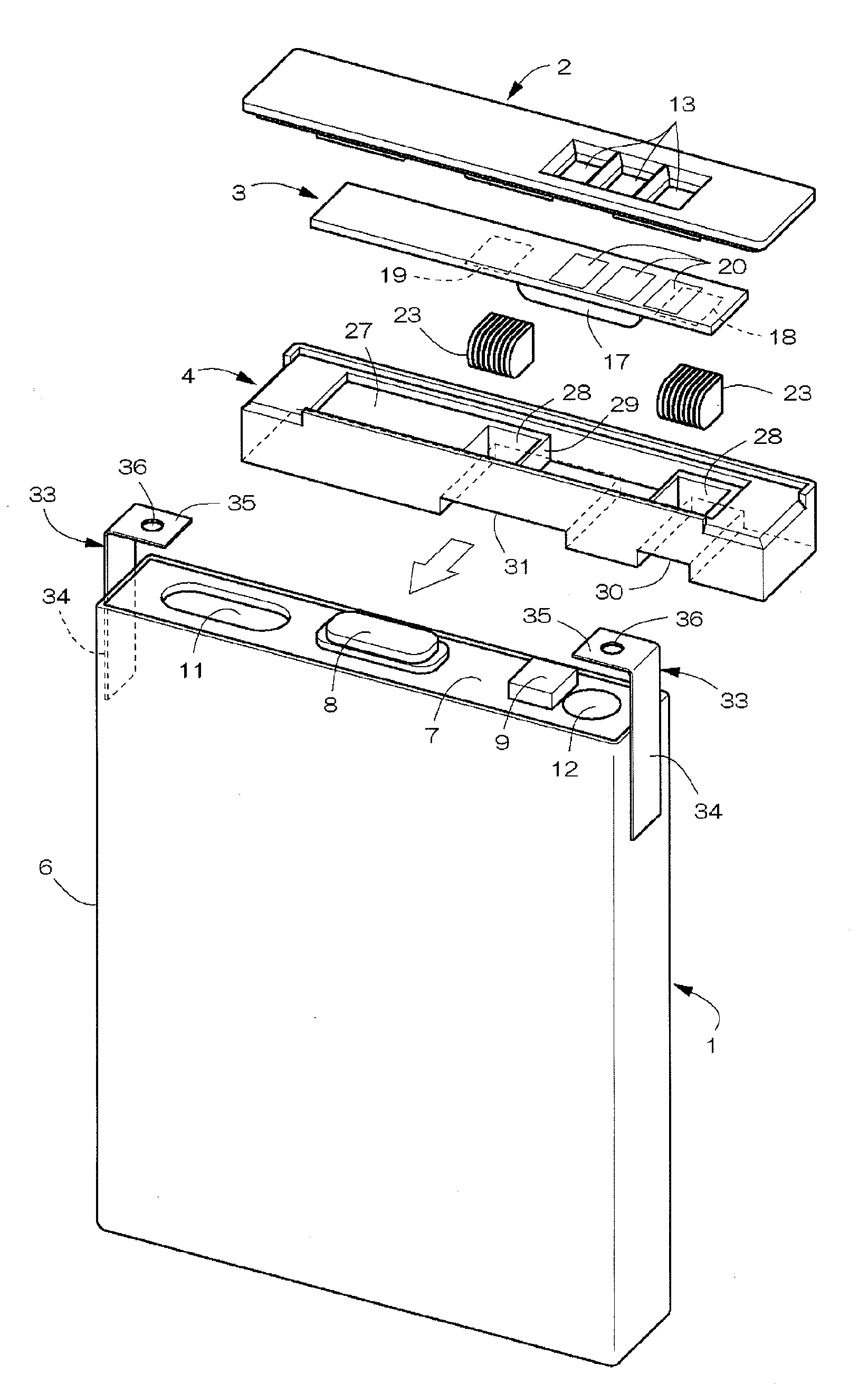
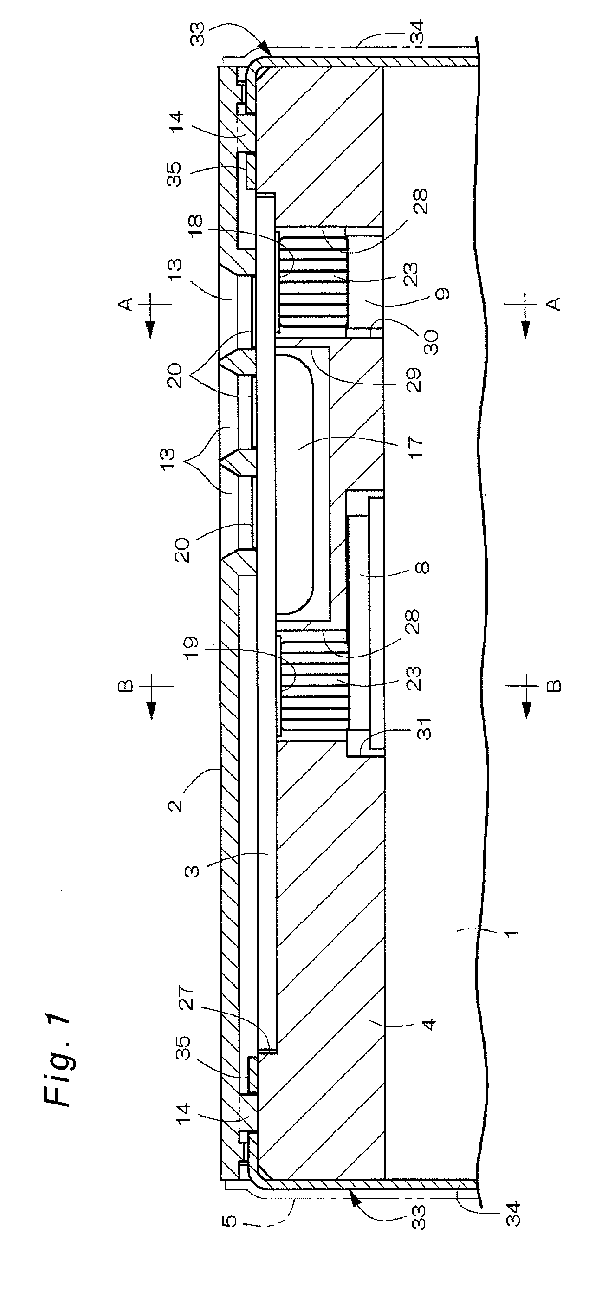
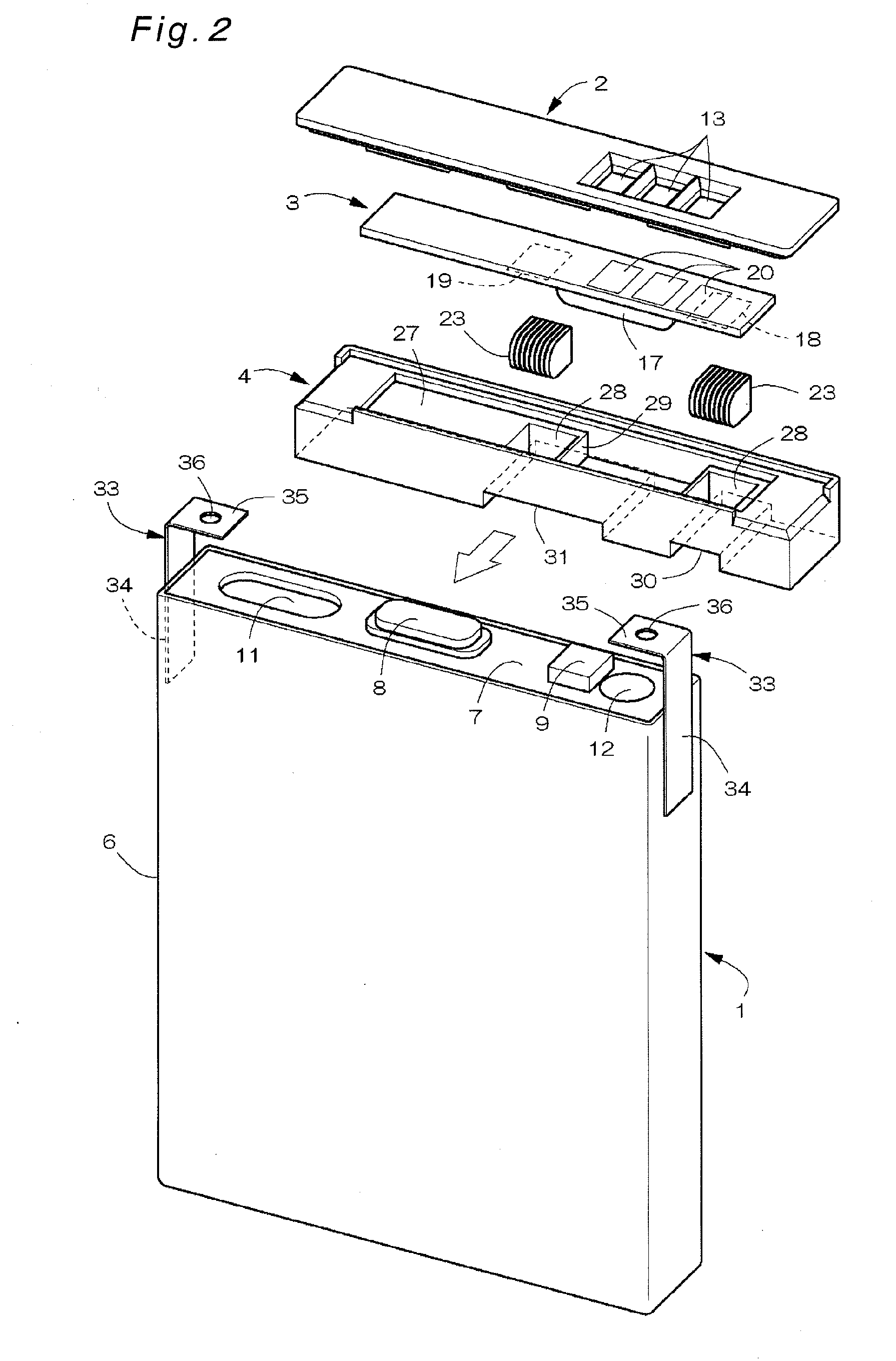
[0055]FIGS. 1 to 7 show a first embodiment of the battery pack according to the invention. Referring to FIG. 2, the battery pack includes a unit cell 1 which is a chargeable / dischargeable secondary battery such as lithium ion battery, an exterior cover 2 placed on the upper surface side of the unit cell 1, a circuit board 3 placed between the unit cell 1 and the exterior cover 2, a holder 4 placed on top of the unit cell 1 to hold the circuit board 3, a facing label 5 (see FIG. 5) for covering outer surfaces of these constituent members, and the like.

[0056]The unit cell 1 includes a bottomed flat cylindrical exterior case 6 as a base body, an electrode body and an electrolyte contained inside, where an upward opening of the exterior case 6 is sealed by a sealing plate 7. The exterior case 6 is formed as a deep-drawn article by using a material of aluminum, aluminum alloy or stainless steel material. The sealing plate 7, which is formed as a press-formed article by using a material o...

second embodiment

[0078]FIGS. 8 and 9 show a second embodiment of the battery pack according to the invention. The second embodiment differs from the first embodiment in that two connectors 23a, 23b are different in height (up-down size) from each other. More specifically, the block piece 9, which is provided in the first embodiment with a view to aligning the height positions of the positive and negative terminals of the unit cell 1, is eliminated, and vertical size of the connector 23a that connects the positive terminals of the unit cell 1 and the circuit board 3 to each other is set larger than the vertical size of the connector 23b that connects their negative terminals to each other. Further, the recessed cutout portion 30 at the lower end of one fitting hole 28 of the holder 4 is omitted. This second embodiment is otherwise similar to the foregoing first embodiment, and therefore like component members are designated by like reference numerals with their description omitted. In this second emb...

third embodiment

[0079]FIGS. 10 and 11 show a third embodiment of the battery pack according to the invention. In this embodiment, the two support members 33 are eliminated from the foregoing first embodiment, and the holder 4 is fixed to the top face of the unit cell 1 (top face of the sealing plate 7) by double-sided tape 40. Front-rear, right-left sizes of the double-sided tape 40 are set slightly smaller than those of the top face of the unit cell 1, and openings 41, 42 for exposing the negative terminal 8 or the block piece (positive terminal) 9 upward are formed at a center of the double-sided tape 40 and its one left / right side end portion (right side end in the example of the figure), respectively. This third embodiment is otherwise similar to the foregoing first embodiment, and therefore like component members are designated by like reference numerals with their description omitted. In this third embodiment also, functional effects similar to those of the first embodiment can be obtained.

[0...


PUM

PropertyMeasurementUnit
diameteraaaaaaaaaa
sizeaaaaaaaaaa
charging currentaaaaaaaaaa

Abstract

Positive and negative terminals formed on a top face of a unit cell and positive and negative terminals formed on a surface of a circuit board opposed to the unit cell are electrically connected to each other by connectors. The connectors each include an elastic body formed from an elastic material, and a conductor which is placed so as to be exposed on upper and lower surfaces of the elastic body and which serves for electrically connecting those exposed portions to each other. By elastic restoring force of the elastic body generated by elastic compression of the elastic body between the terminals, the upper and lower surfaces of the connectors are put into press contact between the opposing positive and negative terminals of the unit cell and the circuit board, by which their electrical connection is maintained.

Description

BACKGROUND OF THE INVENTION[0001]1. Field of the Invention[0002]The present invention relates to a battery pack in which a protection circuit for controlling charging / discharging currents is mounted inside an exterior cover settled at an upper end of a unit cell.[0003]2. Description of Related Art[0004]In this type of battery pack, it is becoming mainstream that a circuit board and a protective device, or positive and negative leads or other electrical components are intensively placed on a sealed surface side of the unit cell. The electrical connection structure between the unit cell and the circuit board for such a kind of battery pack has been proposed in several forms to substitute for spot welding. For instance, in a battery pack disclosed in JP 2006-114468 A, positive and negative terminals of the unit cell and positive and negative terminals of the circuit board are electrically connected to each other by gold-plated, compression coil-type connectors or plate spring-type conn...

Claims


Application Information

Patent Timeline
Patent Type & Authority Applications(United States)
IPC IPC(8): H01M2/02H01M50/147H01M50/574
CPCH01M2/0404H01M2/22H01M10/4257H01M10/42H01M2/34Y02E60/10H01M50/147H01M50/528H01M50/574H01M50/543H01M50/572H01M50/20
Inventor AKATSUCHI, OSAMUYAMAMOTO, HIROSHISUMIDA, TAKASHI
Owner HITACHI MAXELL ENERGY LTD
Why Eureka
Try Eureka