Vehicle assistance system

Inactive Publication Date: 2009-04-02
TOYOTA JIDOSHA KK
View PDF20 Cites 17 Cited by
  • Summary
  • Abstract
  • Description
  • Claims
  • Application Information

AI Technical Summary

Benefits of technology

[0013]According to the present invention, there can be provided the vehicle assistance system capable of solving various defects generated in a case

Problems solved by technology

In addition, when a fuel cell mounted on a fuel cell vehicle fails, any power cannot be supplied to various auxiliary devices.
Therefore, for example, in a case where the fuel cell vehicle is provided with a power steering device operated by power, a problem occurs that the power steering device is not operated owing to the failure of the fuel cell, and it becomes remarkably diffi

Method used


Image

  • Vehicle assistance system
  • Vehicle assistance system
  • Vehicle assistance system

Examples


Embodiment Construction

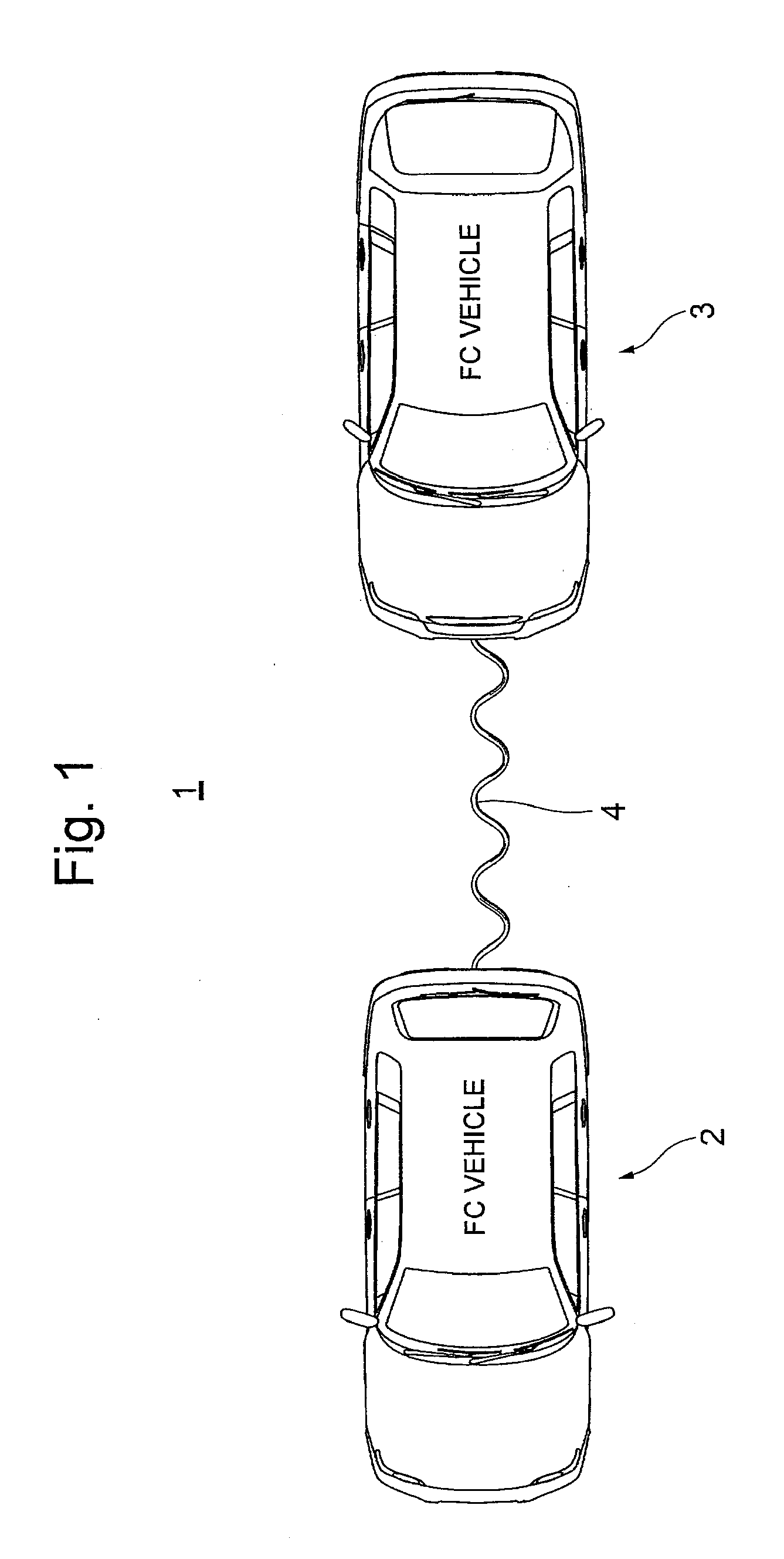
[0017]A vehicle assistance system 1 according to an embodiment of the present invention will hereinafter be described with reference to the drawings. In the present embodiment, the system will be described in which two fuel cell vehicles are connected to each other via an electric cable and in which when a fuel cell mounted on one of the fuel cell vehicles fails, the power of a fuel cell mounted on the other fuel cell vehicle (an assistance vehicle) is supplied to the one fuel cell vehicle (an assisted vehicle) via the electric cable.

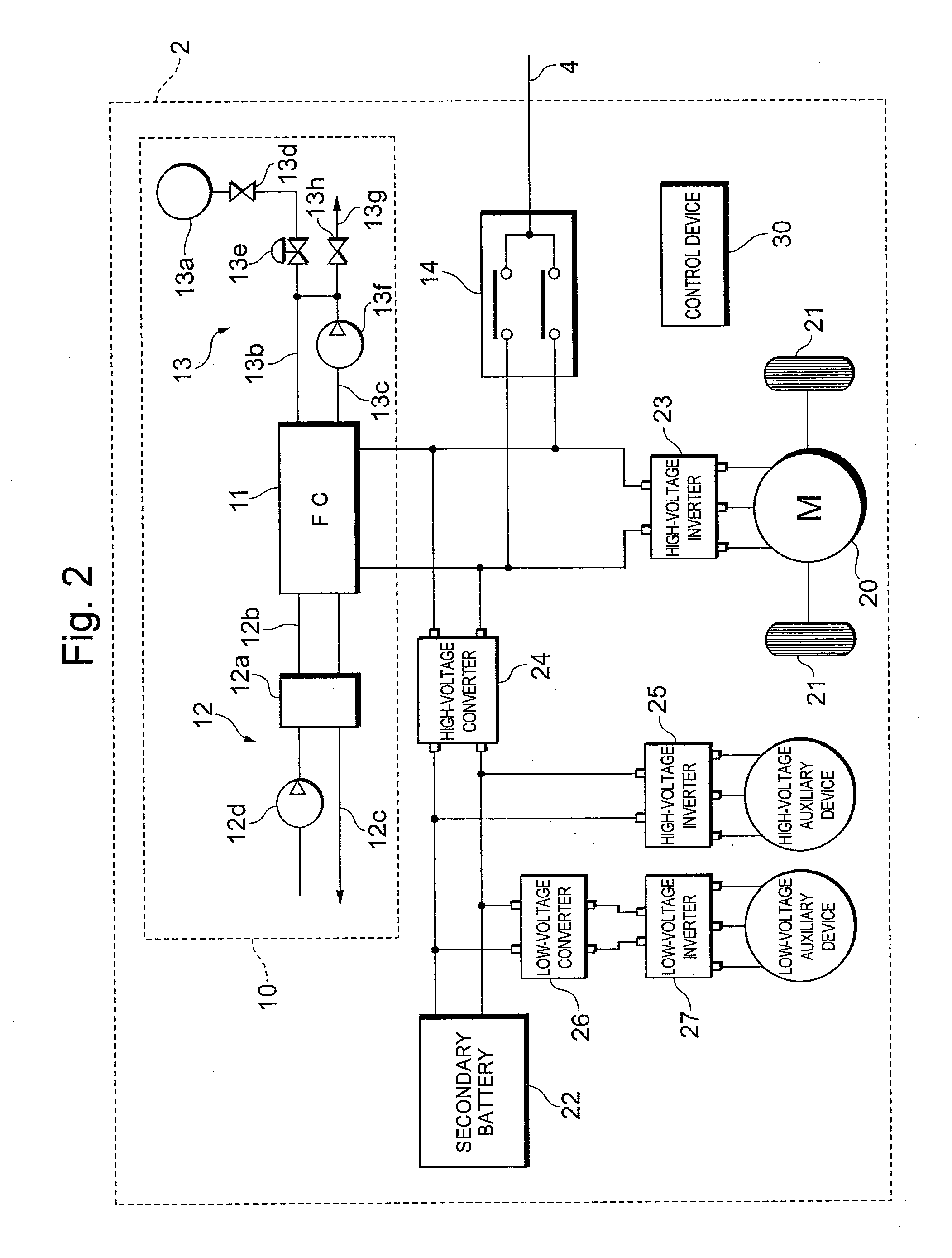
[0018]First, the constitution of the vehicle assistance system 1 according to the present embodiment will be described with reference to FIGS. 1 and 2. As shown in FIG. 1, the vehicle assistance system 1 includes a first fuel cell vehicle (hereinafter referred to as the “first vehicle”) 2, a second fuel cell vehicle (hereinafter referred to as the “second vehicle”) 3, and an electric cable 4 which electrically connects these vehicles to each other.

[0019...


PUM


Abstract

There is disclosed a vehicle assistance system including an assistance vehicle provided with a power source; an assisted vehicle driven by power; and an electric cable which electrically connects the assistance vehicle to the assisted vehicle, wherein the power of the power source is supplied from the assistance vehicle to the assisted vehicle via the electric cable.

Description

TECHNICAL FIELD[0001]The present invention relates to a vehicle assistance system.BACKGROUND ART[0002]At present, a fuel cell vehicle which runs when driven by the power of a fuel cell as a driving source has been suggested and put to practical use, the fuel cell being configured to receive the supply of a reaction gas (a fuel gas and an oxidizing gas), thereby generating the power. When a certain defect occurs in the fuel cell as the driving source of such a fuel cell vehicle, energy for driving cannot be obtained.[0003]To solve the problem, in recent years, various technologies for towing the fuel cell vehicle having failure have been suggested. For example, a technology is suggested which employs an emergency switch for unlocking the tires of the fuel cell vehicle to be towed so that the tires can freely rotate (e.g., see Japanese Patent Application Laid-Open No. 2005-119330).DISCLOSURE OF THE INVENTION[0004]In addition, when a fuel cell mounted on a fuel cell vehicle fails, any ...

Claims


Application Information

Patent Timeline
IPC IPC(8): B60L9/00H01M50/503
CPCB60L3/00Y02E60/50B60L3/12B60L11/1803B60L11/1868B60L11/1887B60L15/38B60L2210/12B60L2210/14B60L2210/30B60L2210/40B60W10/28B60W20/00H01M2/206H01M8/04626H01M8/0494H01M8/04947H01M16/006H01M2250/20Y02T10/7066Y02T10/7225Y02T10/7233Y02T10/7241Y02T90/32Y02T90/34B60L3/0053B60L50/51B60L58/20B60L58/40Y02T10/70Y02T10/72Y02T90/40Y02E60/10H01M50/503B60W2510/28B60W10/08B60K6/32
Inventor KIZAKI, MIKIO
Owner TOYOTA JIDOSHA KK
Why Eureka
Try Eureka