
Accessory-testing device and method therefor

a testing device and accessory technology, applied in the direction of testing circuits, instruments, marginal checks, etc., can solve the problems of consuming a lot of time, limited functions, damage to the host device, etc., to reduce the operating space, reduce the inspection time, and improve production efficiency

Inactive Publication Date: 2009-04-02
INVENTEC CORP
View PDF4 Cites 3 Cited by
  • Summary
  • Abstract
  • Description
  • Claims
  • Application Information

AI Technical Summary

Benefits of technology

[0007]In view of the above problems, the present invention provides an accessory-testing device for an information processing apparatus to reduce the inspection time, reduce the operating space, and improve the production efficiency.
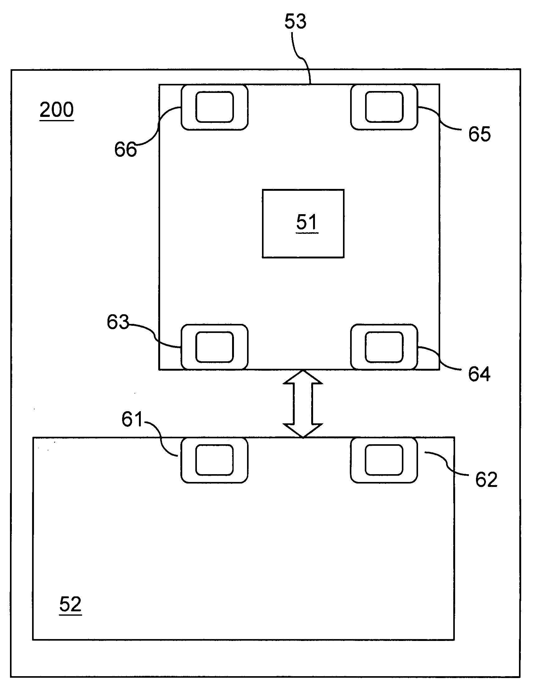
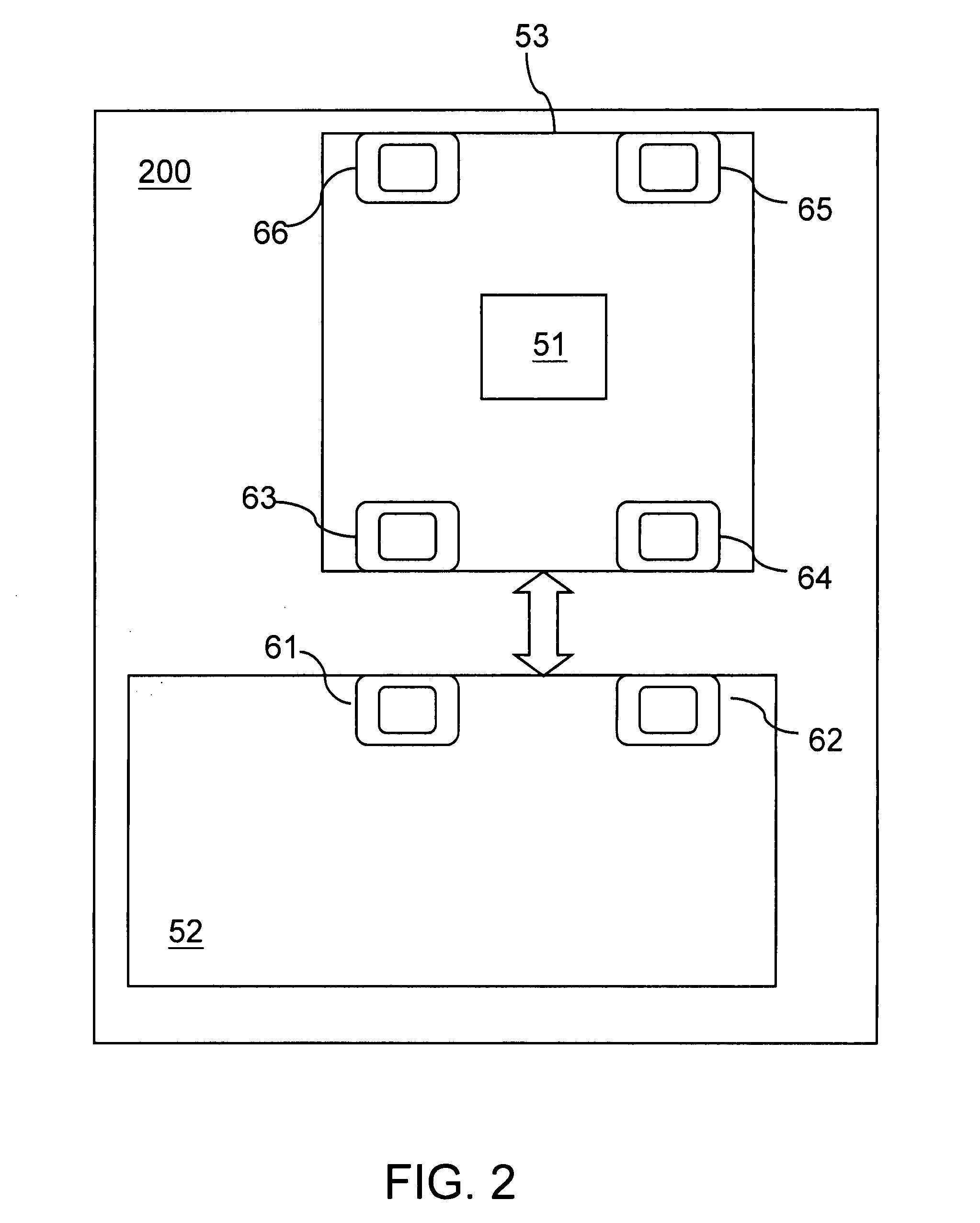
[0009]The accessory-testing device uses an MPU to send the mimic signal that mimic a signal simulating an operation of a component in the information processing apparatus, and a signal conversion unit to convert the mimic signal into a test signal to test the accessory. The accessory receives the test signal and then outputs a feedback signal in response to the test signal. The feedback signal is received by the signal conversion unit and then transmitted to the MPU, such that the MPU determines whether the accessory operates normally according to the feedback signal. The deficiencies of the conventional testing methods are eliminated from the above test process, and the inspection time of the accessory under test is reduced, thus improving the production efficiency.

Problems solved by technology

The earliest information processing apparatus mainly uses vacuum tubes, and has limited functions due to the large volume and poor heat dissipation effect.
This inspection manner requires the assembly of the complete apparatus and the installation of a software system, thus consuming much time.
Moreover, frequent plugging / unplugging of the accessories may damage the host device.
Some accessories need the monitoring of external errors, so the inspection of the complete apparatus cannot be simulated.
Further, the inspection environment needs a large working space.

Method used


Image

  • Accessory-testing device and method therefor
  • Accessory-testing device and method therefor
  • Accessory-testing device and method therefor

Examples


Embodiment Construction

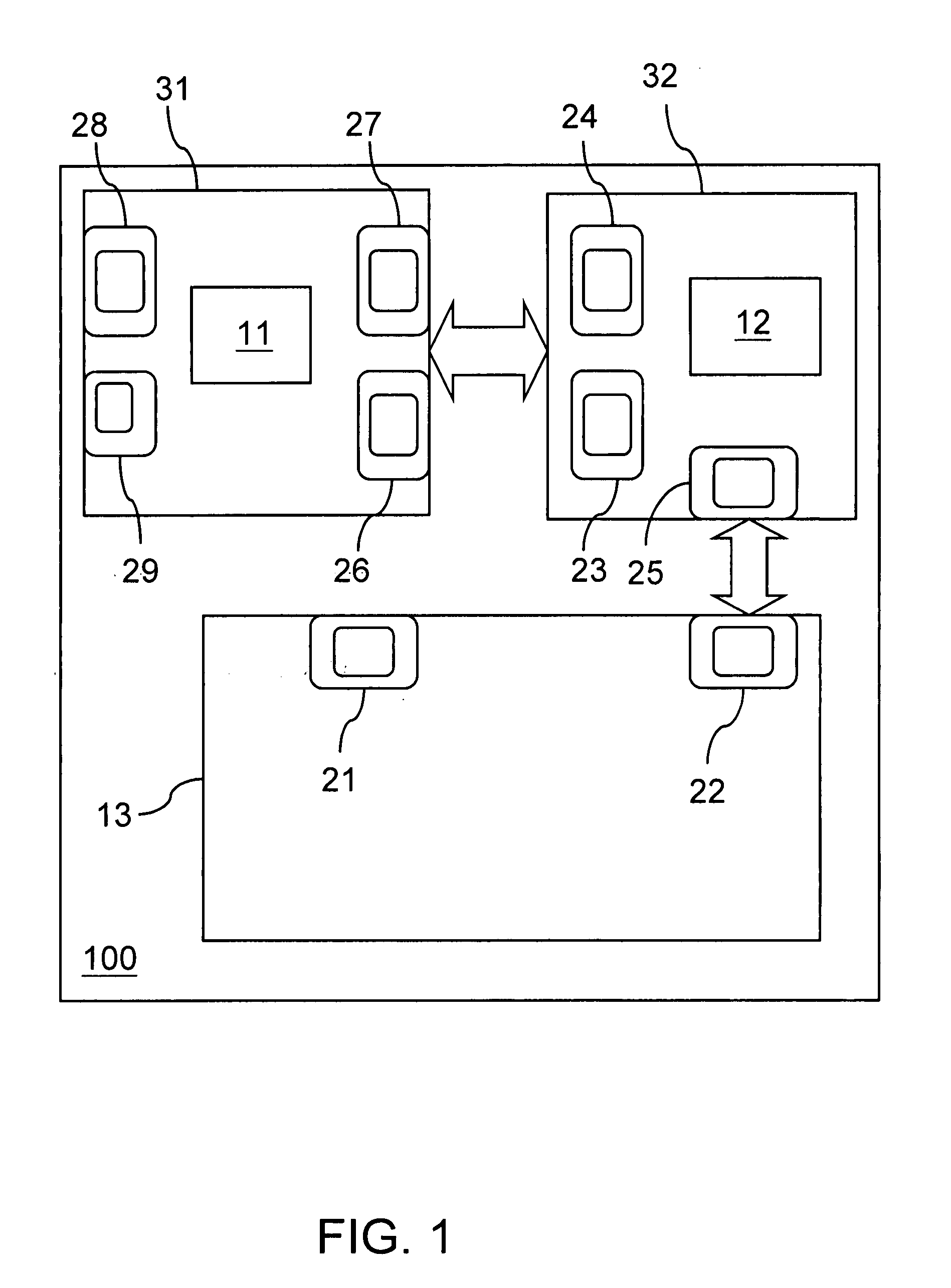
[0015]FIG. 1 is a schematic view of an accessory-testing device according to the present invention. Referring to FIG. 1, the accessory-testing device 100 includes an MPU 11, a signal conversion unit 12, an accessory 13, a first circuit board 31, and a second circuit board 32.

[0016]The accessory 13 has, but not limited to, an inter integrated circuit (I2C) signal transmission interface 21 and a general purpose input / output (GPIO) signal transmission interface 22, or other connection interfaces. The accessory 13 receives the test signal and then outputs a feedback signal in response to the test signal. The accessory 13 may be an LED board, a fan board, or an SAS BP board. The LED board is used to indicate the state of the host device, the result of the temperature inspection, and the ON / OFF state of the key. The SAS BP board is connected to an SAS hard drive and controls the working state indicator of the hard drive. The fan board is used to control and inspect the operation of the fa...


PUM


Abstract

An accessory-testing device for an information processing apparatus includes a micro-processing unit (MPU) and a signal conversion unit. The MPU sends a mimic signal. The signal conversion unit is electrically connected to the MPU and an accessory respectively, for receiving the mimic signal and converting the mimic signal into a test signal to test the accessory. The accessory receives the test signal and then responds to the test signal to output a feedback signal. The feedback signal is received by the signal conversion unit and transmitted to the MPU, such that the MPU determines if the accessory operates normally according to the feedback signal. Conventional testing methods are Therefore, it is achieved that the effects of reducing the inspection time and improving the production efficiency.

Description

BACKGROUND OF THE INVENTION[0001]1. Field of Invention[0002]The present invention relates to an accessory-testing device for an information processing apparatus, and more particularly to an accessory-testing device and method therefor that utilizes a mimic signal that mimics a signal for simulating an operation of a component in an information processing apparatus to test an accessory.[0003]2. Related Art[0004]The earliest information processing apparatus mainly uses vacuum tubes, and has limited functions due to the large volume and poor heat dissipation effect. In order to eliminate those deficiencies, transistors are put forward to reduce the volume of the information processing apparatus system. After the integrated circuit (IC) has been developed, many transistors may be arranged on a thumbnail area. Later, in the times of microprocessors, the number of the transistors on a unit area in an IC is increased to several hundred thousand or above, so the volume of the information pr...

Claims


Application Information

Patent Timeline
Patent Type & Authority Applications(United States)
IPC IPC(8): G06F19/00
CPCG06F11/24
Inventor HAN, XUE-SHANZHENG, QUAN-JIESONG, JEFFJIN, JHIH-RENCHEN, TOMLIU, WIN-HARN
Owner INVENTEC CORP
Learn More