

Granular thermal energy storage mediums and devices for thermal energy storage systems
a technology of thermal energy storage and granular thermal energy, which is applied in the direction of steam engine plants, machines/engines, collectors with underground reservoirs, etc., can solve the problems of disproportionately high fabrication and material costs, imposing formidable construction and cost constraints, and reducing the volumetric capacity of the vessel. achieve the effect of round the clock supply
Inactive Publication Date: 2009-04-09
AREVA SOLAR
View PDF4 Cites 101 Cited by
- Summary
- Abstract
- Description
- Claims
- Application Information
AI Technical Summary
Benefits of technology
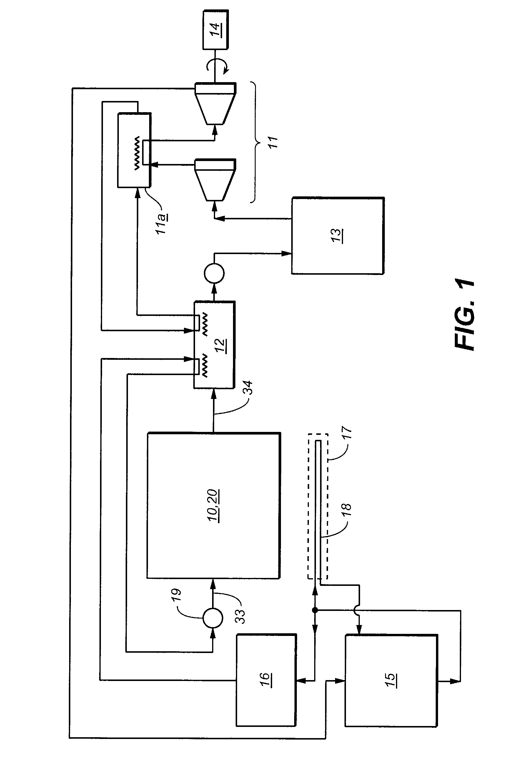
[0027]In use of the invention (in its various aspects) as above defined, thermal energy from the working fluid is transferred to and stored in the energy storage system for use as and when required. Additionally, excess thermal energy from the working fluid may be transferred to and stored in the energy storage system when the available thermal energy exceeds load power demand, under either static or dynamic conditions. Thus, depending upon the storage capacity of the energy storage system, the system may be employed as a short-term buffer system or as a system that facilitates round the clock supply when using a discontinuous heating system such as that available from solar radiation.
Problems solved by technology
These requirements impose formidable construction and cost constraints.
However, the fabrication and material costs inherent in building a vessel having the volumetric capacity required for storage of sufficient working fluid to provide for sustained fluid mass flow rates has been determined to be disproportionately high relative to other components of a total power generating system.
In the third type of storage, cracks occur in the concrete encasement due to differential expansion between the concrete and the pipes.
This leads to the appearance of gaps between the pipes and the concrete and, consequently, poor heat transfer (in both directions) between the pipes and the concrete due to increased thermal resistance.
Cracks in the concrete also cause thermal islands which cannot usefully participate in thermal energy storage.
The fifth type of storage was rejected in the 1980s, due to low thermal conductivity, as the number of interfaces between the grains of sand reduce thermal conductivity, and higher costs, as more closely spaced pipes were required.
Method used
View moreImage
Smart ImageViewing Examples

Examples
example
[0142]The conductivity of topsoil from Carrizo Plains was measured. The soil was alluvium formed from quartzite, basalt and shale. At low temperature (approx 50° C.) the surface soil conductivity was 0.34 W / (m·K). Surprisingly, the conductivity at 250° C. was greater, 0.49 W / (m·K).
[0143]A mixture of 21% Carrizo Plains topsoil plus 79% quartzite rounded pebbles of nominal size 38 mm (one and a half inch) resulted in a conductivity of 0.78 W / (m·K) at 250° C.
Login to View More PUM
 Abstract
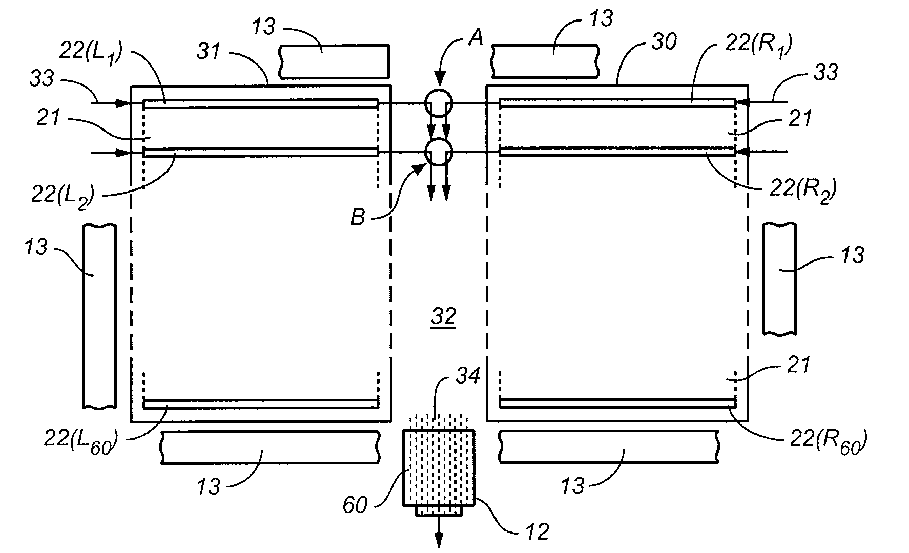
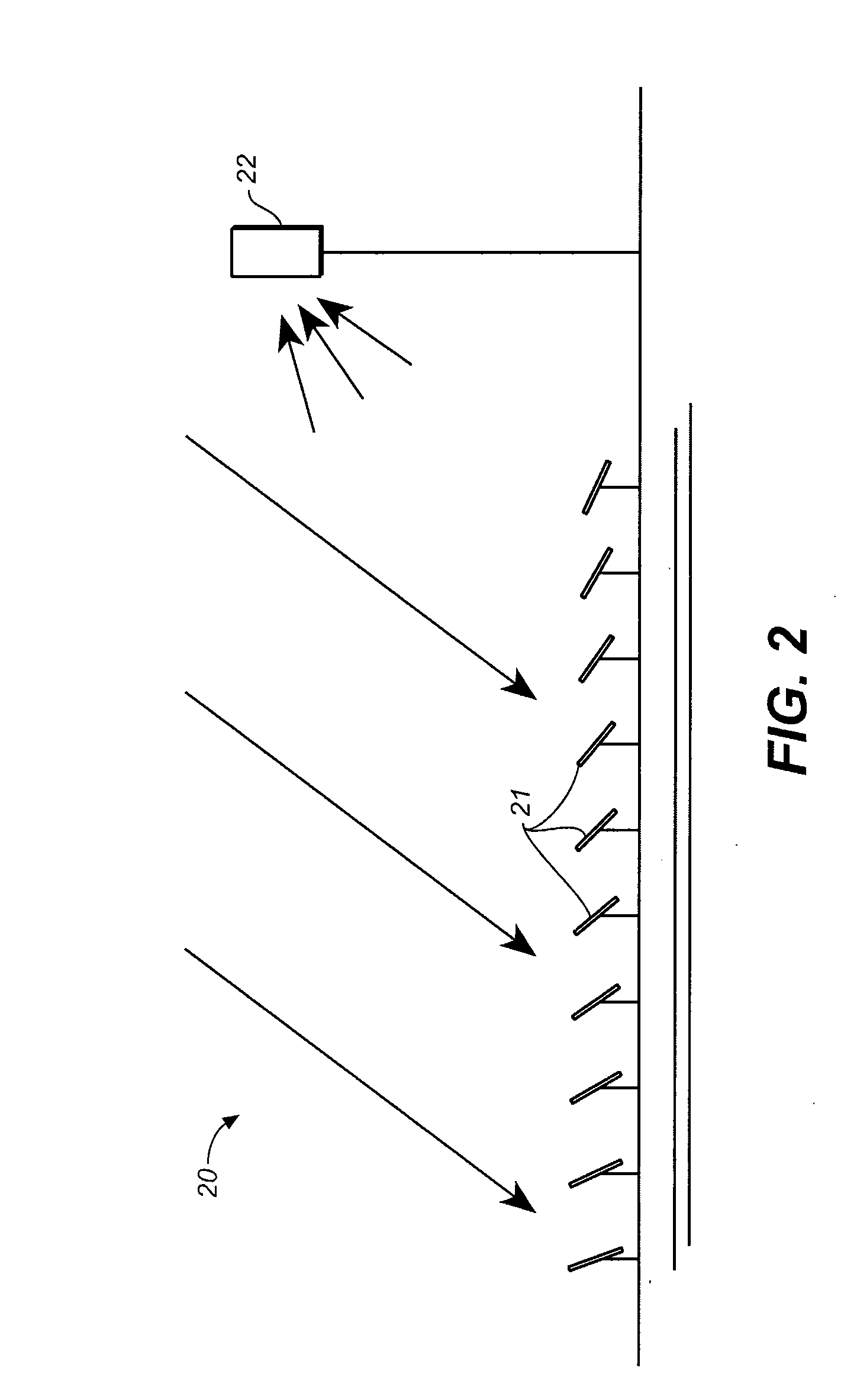
The invention provides compositions for use in thermal energy storage systems, including thermal energy storage mediums, fluid channeling devices and thermally conductive heat transfer elements, and methods for storing thermal energy. A thermal energy storage system is provided, comprising: (a) a granular thermal energy storage medium comprising at least a first size class and a second size class; wherein the individual granules of each size class deviate from the average granular size for that size class by no more than about ±50%; wherein first size class is the largest size class; wherein the ratio of the average size of the first size class to the average size of the second size class is at least about 2:1; and (b) one or more conduits disposed within the medium, and arranged to receive a source of thermal energy.
Description
CROSS-REFERENCE TO RELATED APPLICATIONS[0001]This application claims the benefit under 35 U.S.C. § 119(e) of U.S. Provisional Applications Ser. Nos. 60 / 933,648, 60 / 933,615 and 60 / 933,637 all three filed Jun. 6, 2007, the contents of which are incorporated herein by reference in their entirety.BACKGROUND OF THE INVENTION[0002]Thermal energy storage systems are, in various circumstances, required to be incorporated in thermal power plants, including those that employ nuclear reactors, package boilers and solar energy collector systems. The thermal energy storage systems may be required as buffers against transient demands that exceed the steady state output capacities of plants, against temporary reduction in input heat or, alternatively, to provide long term thermal energy storage when heat generating capabilities cannot, for various reasons, be synchronized with load demands. One or the other or all of these requirements may exist in relation to thermal power plants, including those...
Claims
Login to View More Application Information
Patent Timeline
 Patent Type & AuthorityApplications(United States)
IPC IPC(8): F01K3/00F28F7/00F03B11/00
CPCF24J3/081F24J2002/1076Y02E60/142Y02E10/12F28D20/0056F24T10/10F24S2023/87Y10T137/8593F24T10/30Y02E10/10Y02E60/14
InventorMILLS, DAVID R.MIERISCH, ROBERT C.
OwnerAREVA SOLAR