Night sky cooling system

a cooling system and night sky technology, applied in the field of cooling system, can solve the problems of large electricity consumption, complex systems, and high cost, and achieve the effects of reducing energy consumption, reducing energy consumption, and reducing energy consumption

Inactive Publication Date: 2009-04-09
MCNNNAC ENERGY SERVICES
View PDF15 Cites 23 Cited by
  • Summary
  • Abstract
  • Description
  • Claims
  • Application Information

AI Technical Summary

Benefits of technology

[0021]In one embodiment the heat exchange element comprises finned cooling coils. In one embodiment there is a single stratified storage tank that is used to hold both warmed and cooled water. In one embodiment, there is an additional hea

Problems solved by technology

Conventional chiller units can quickly cool the interior of a structure, but they consume large quantities of electricity, particularly when ambient temperature and humidity are high.
Absorptive refrigerators are popular in situations where electricity is unreliable, costly, or unavailable, where noise from the compressor is problematic, or where surplus heat is readily available.
These systems are effective but are complex, expensive and require the use of potentially harmful materials.
Like conventional chiller units, DX systems can quickly cool the interior of a structure, but they consume large quantities of electricity, particularly when ambient temperature and humidity a

Method used


Image

  • Night sky cooling system
  • Night sky cooling system
  • Night sky cooling system

Examples


example 1

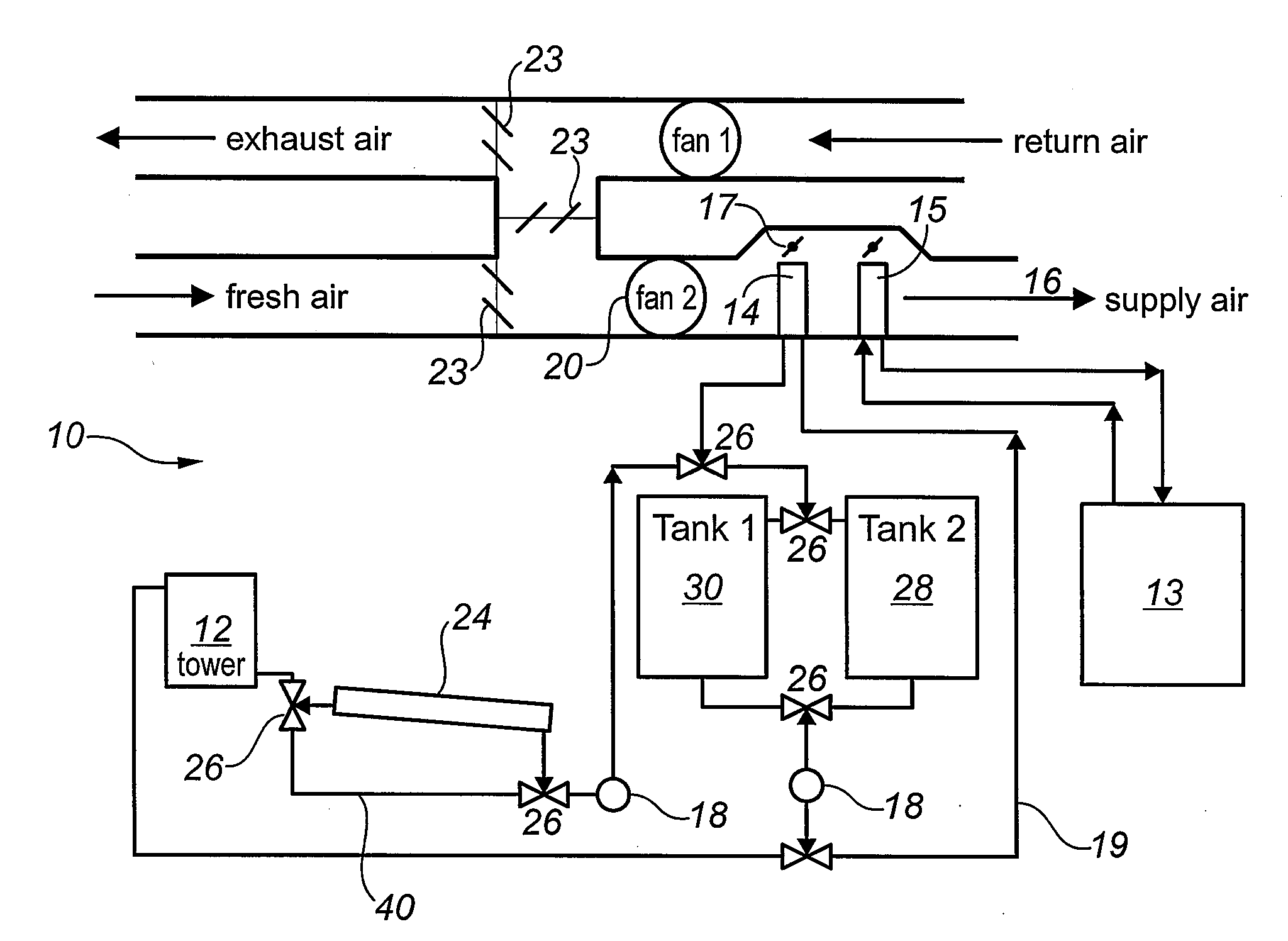
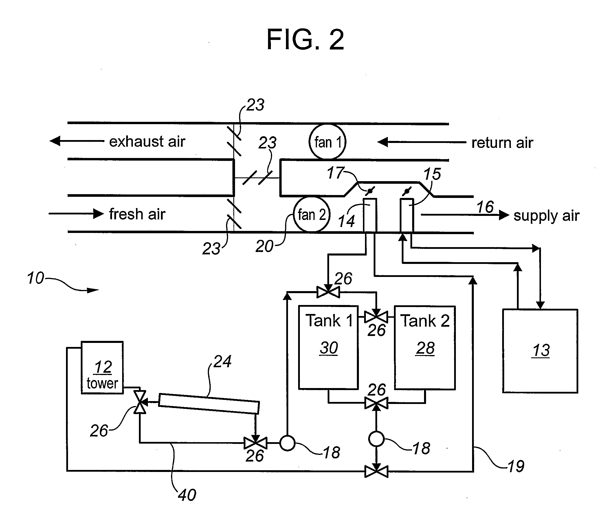
[0073]Operation of the system as depicted in FIG. 3 having a single cooling tower (12), a night sky cooler (24), two storage tanks (28,30) and a single heat exchange element (14).

[0074]The sequence of operation at night for night time cooling and storage is as follows. Assuming that the first tank (30) is full of spent (warn) water, the cooling tower (12) is activated and valve V4 is opened to allow the flow of water from tank (30) to pump P2. Pump P2 is started and valve V3 is opened to allow the flow of water to the cooling tower (12) where water is cooled. Valve V1 is closed to allow the flow of water from the cooling tower (12) to the night sky cooler (24). Further cooling is achieved in the night sky cooler (24) by means of heat radiation to space. Valve V2 is opened to allow night sky cooler (24) discharge to flow to pump P1. Valve V7 is opened to allow flow to valve V5 and to the second tank (28), being the empty tank in this case which will be used to store the cooled water ...

example 2

[0076]Operation of the system as depicted in FIG. 5 having a cooling tower (12), a night sky cooler (24), two storage tanks (28,30) and a single heat exchange element (14) and a second evaporative cooling system (60).

[0077]The sequence of operation for night cooling and storage is as follows. Assuming that the first tank (30) is full of spent (warm) water, the cooling tower (12) is activated and valve V4 is opened to allow the flow of water from the first tank (30) to pump P2. Pump P2 and pump P3 are started and valve V3 is opened to allow the flow of water to the primary cooling tower (12) where water is cooled. The air supply to the primary cooling tower (12) is pre-cooled by the second evaporative cooling system (60). Discharge from the cooling tower (12) flows to valve V1 which is closed to allow flow to the night sky cooler (24) and further cooling of the water is achieved through heat radiation to space. Valve V2 is opened to allow discharge from the night sky cooler (24) to f...

example 3

[0079]Operation of the system as depicted in FIG. 7 having a cooling tower (12), a night sky cooler (24), two storage tanks (28,30) and a single heat exchange element (14) and a second (60) and third (70) evaporative cooling system.

[0080]The sequence of operation for night cooling and storage is as follows. Assuming that the first tank (30) is full of spent (warm) water, then the cooling tower (12) is activated and valve V4 is opened to allow flow from the first tank (30) to pump P2. Pump P2 is started and valve V3 is opened to allow the flow of water to the primary cooling tower (12) where water is cooled. Discharge from the cooling tower (12) flows to valve V1 which is closed to allow the flow of water to the night sky cooler (24) where further cooling is achieved by radiation to space. Valve V2 is opened to allow the flow of water from the night sky cooler (24) to pump P1. Pump P1 is activated with valve V7 opened to direct flow to valve V5. Valve V5 is opened to allow flow into ...


PUM


Abstract

A cooling system that can be used to cool water and to cool an air supply to a building. The system employs a stand alone cooling tower and a night sky cooler. As a result, the water can be cooled below the ambient wet bulb temperature.

Description

FIELD OF THE INVENTION[0001]The present invention relates to a system for cooling water, and in particular to a system for cooling water to be used to cool the air supply to a building.BACKGROUND[0002]Conventional chiller units are commonly used to cool the air supply to a building. In a compression type conventional chiller, vaporized refrigerant is compressed in a compressor which causes the refrigerant to heat up. The hot gas is directed to the condenser where the refrigerant is cooled and condenses. Typically the condenser is cooled by water or air. Many such chiller systems utilize cooling towers to provide a supply of cooled water to the condenser to absorb rejected heat. The liquid refrigerant from the condenser passes through an expansion valve into the evaporator. As the fluid passes through the expansion valve, the pressure of the refrigerant is reduced causing vaporization of the liquid, which results in a large reduction in temperature. The cold refrigerant in an evapora...

Claims


Application Information

Patent Timeline
IPC IPC(8): F28D15/00
CPCF24F5/0035F24F5/0046F28C1/02F28C1/04Y02B30/545F28D15/00Y02B10/20Y02B10/24F28C2001/006Y02B30/54Y02B30/70Y02A30/272
Inventor MCCANN, NEIL
Owner MCNNNAC ENERGY SERVICES
Why Eureka
Try Eureka