Sensing System

a technology of sensing system and touch system, which is applied in the direction of mechanical pattern conversion, optical conversion of sensor output, instruments, etc., can solve the problems of relatively high production cost of each of the touch system disclosed in the patents, and achieve the effect of low production cos

Inactive Publication Date: 2009-04-09
PIXART IMAGING INC
View PDF8 Cites 51 Cited by
  • Summary
  • Abstract
  • Description
  • Claims
  • Application Information

AI Technical Summary

Benefits of technology

[0009]The present invention is directed to provide a sensing system of which the production cost is relatively low.
[0021]The processor of the sensing system of the embodiment of the present invention can calculate the location of the pointer by means of employing the reflective element and the image sensor. Therefore, compared with the conventional arts, the sensing system of the present embodiment can employ one image sensor such that the production cost thereof is low.

Problems solved by technology

Each of the touch systems disclosed in the above two patents must have at least two sensors, such that the production cost of each of the touch systems disclosed in the patents is relatively high.
However, the conventional touch screen system 100 must have the two photosensors 120 and 130, such that the production cost thereof is relatively high.

Method used


Image

  • Sensing System
  • Sensing System
  • Sensing System

Examples


first embodiment

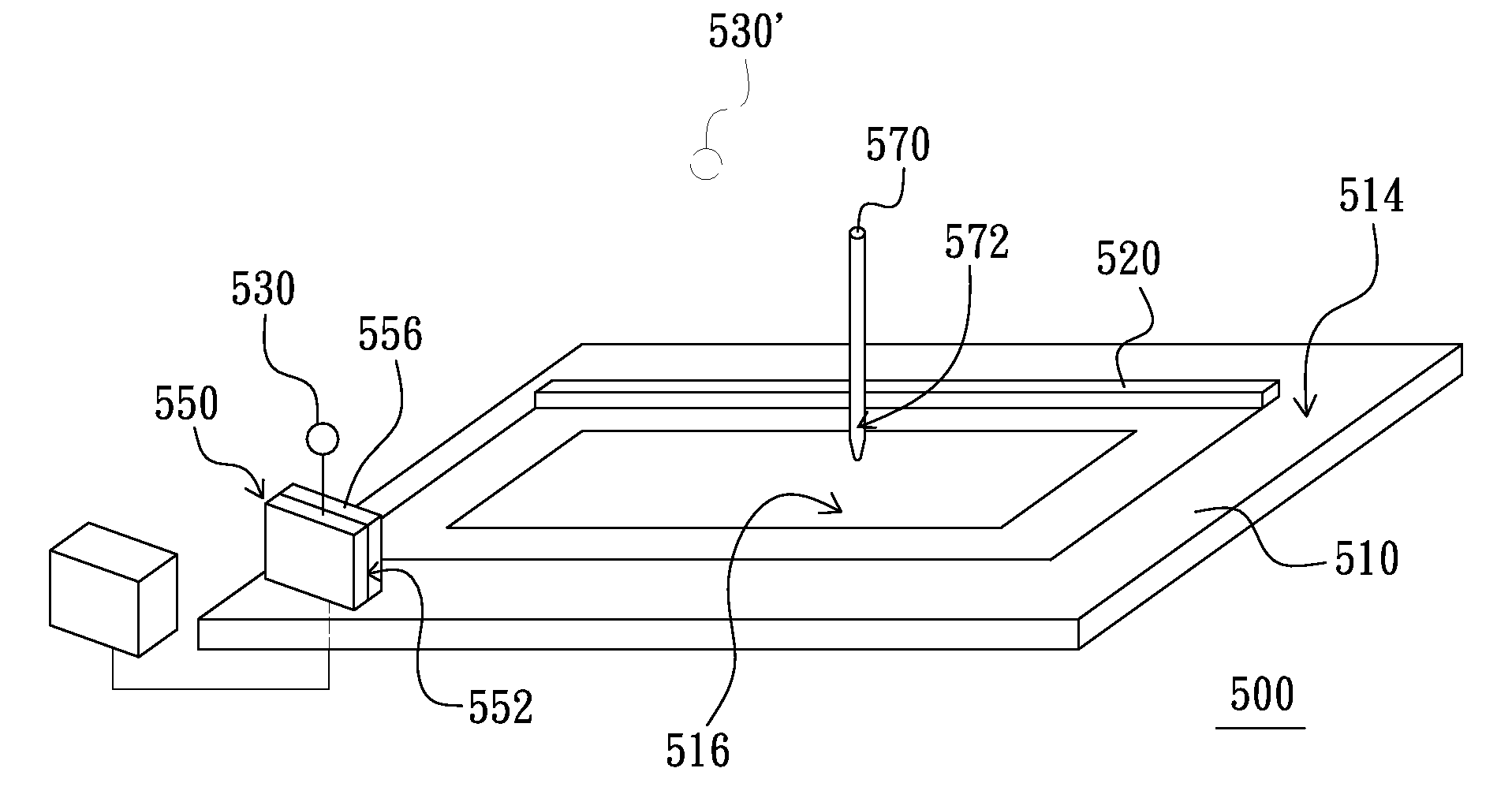
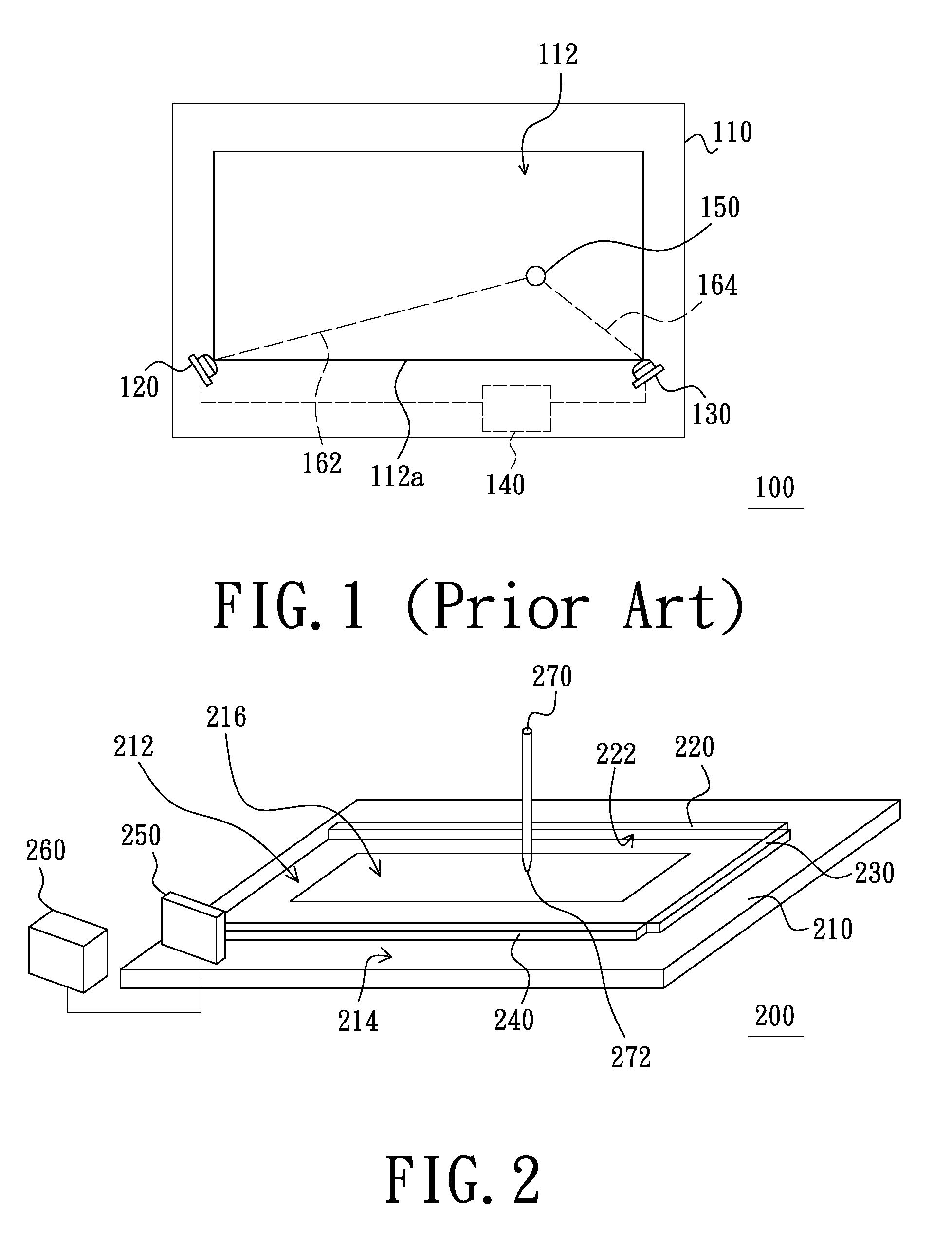
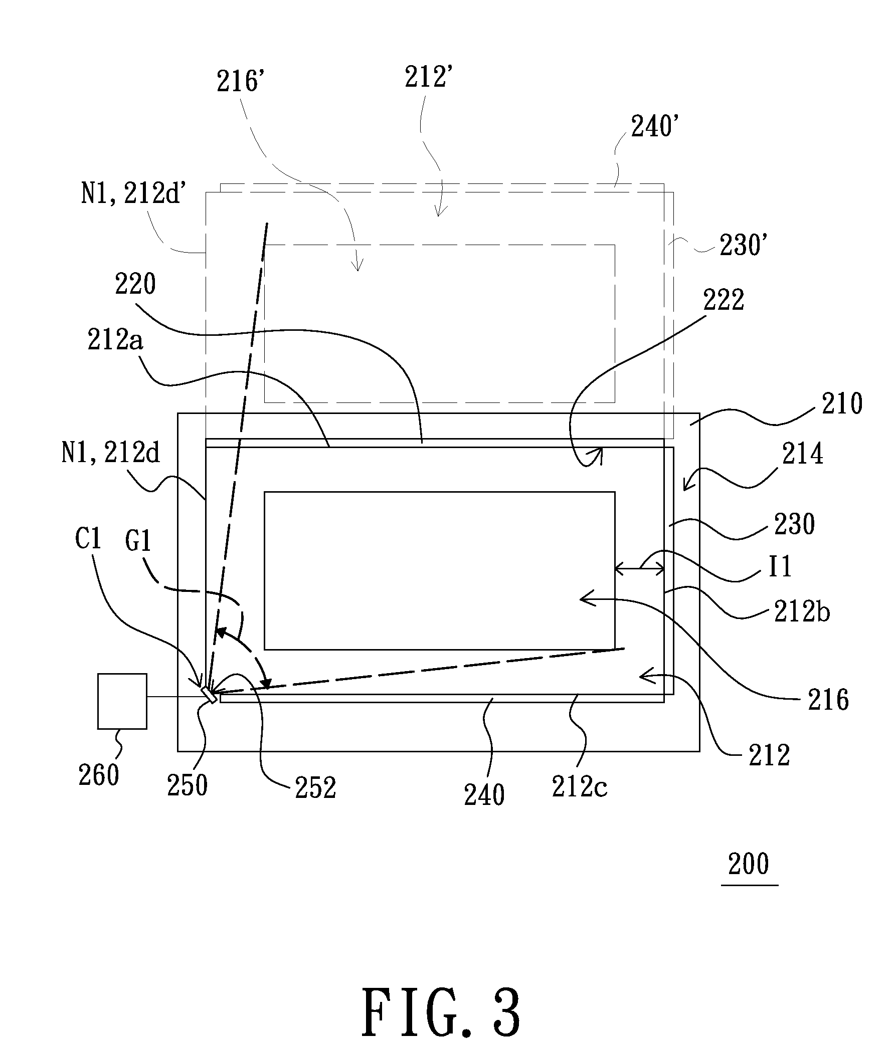
[0034]FIG. 2 is a schematic three-dimensional view of a sensing system of a first embodiment of the present invention. FIG. 3 is a schematic top view of the sensing system of FIG. 2 in operation. Referring to FIGS. 2 and 3, the sensing system 200 is adapted to sensing a pointer 270 and calculating the location of the pointer 270 (seeing the following detailed description). The sensing system 200 includes a panel 210, a reflective element 220, a first linear light source 230, a second linear light source 240, an image sensor 250 and a processor 260. The panel 210, such as a whiteboard or a touch screen, has a first plane 214, a first area 212 located at the first plane 214 and a third area 216 located at the first plane 214. The third area 216 is located in the first area 212. The first area 212 is quadrangular, such as a rectangle. Furthermore, the first area 212 has a first boundary 212a, a second boundary 212b, a third boundary 212c and a fourth boundary 212d which are connected i...

second embodiment

[0044]FIG. 6 is a schematic top view of a sensing system of a second embodiment of the present invention. Referring to FIGS. 3 and 6, the difference between the sensing system 300 of the present embodiment and the sensing system 200 of the first embodiment lies in that two of the boundaries of the third area 316 of the panel 310 of the sensing system 300 coincide with the third boundary 312c and the second boundary 312b of the first area 312 respectively. To sum up, an interval I2 is located between the third area 316 and the first area 312 and the interval I2 is L-shaped.

third embodiment

[0045]FIG. 7 is a schematic top view of a sensing system of a third embodiment of the present invention. Referring to FIGS. 3 and 7, the difference between the sensing system 400 of the present embodiment and the sensing system 200 of the first embodiment lies in that the third area 416 of the panel 410 of the sensing system 400 is quadrangular and not a rectangle.


PUM


Abstract

A sensing system includes a panel, a reflective element (RE), an image sensor (IS) and a processor electrically connected to the IS. The panel has a plane, a first area (FIA) having the first, second, third and fourth boundaries connected in order and a third area (TA) at the plane. The TA in the FIA is smaller than the FIA. The FIA and TA are quadrilaterals. The RE on the plane is disposed at the first boundary. A reflective mirror plane (RMP) of the RE perpendicular to the plane mirrors the FIA and TA to form a second area (SA) and a fourth area (FOA). The IS sensing the TA and FOA on the plane is disposed at the intersection of the third and fourth boundaries. An imaginary line passing through the IS, being perpendicular to the RMP and being located on the plane is outside the TA and FOA.

Description

RELATED APPLICATIONS[0001]This application is a continuation-in-part of U.S. patent application Ser. No. 11 / 249,222 filed on Oct. 10, 2008.BACKGROUND[0002]1. Field of the Invention[0003]The present invention relates to a sensing system, and more particularly, to a sensing system having a reflective element.[0004]2. Description of the Related Art[0005]Touch systems have been disclosed in many patents, such as U.S. Pat. No. 4,782,328 and U.S. Pat. No. 6,803,906. Each of the touch systems disclosed in the above two patents must have at least two sensors, such that the production cost of each of the touch systems disclosed in the patents is relatively high. One of the two patents is described thereinafter in detail.[0006]FIG. 1 is a schematic view of a conventional touch screen system. Referring to FIG. 1, the touch screen system 100 disclosed in the U.S. Pat. No. 4,782,328 includes a panel 110, a first photosensor 120, a second photosensor 130 and a processor 140. The panel 110 has a t...

Claims


Application Information

Patent Timeline
Patent Type & Authority Applications(United States)
IPC IPC(8): G06F3/042G08C21/00
CPCG01D5/28H04W92/18H04W88/04G06F3/0421
Inventor LIN, CHO-YI
Owner PIXART IMAGING INC
Why Eureka
Try Eureka