Airfield lighting with LED

Inactive Publication Date: 2009-04-09
SAFEGATE INT
View PDF9 Cites 21 Cited by
  • Summary
  • Abstract
  • Description
  • Claims
  • Application Information

AI Technical Summary

Benefits of technology

[0024]The inventive airfield lighting unit may comprise any of the features describ

Problems solved by technology

Otherwise, the consequences of a plane missing a taxiway or a stop signal can be disastrous.
Since visual light source inspection increases the risk for an accident and induce costs, automatic lamp monitoring systems have been developed.
Present solutions for supplyi

Method used


Image

  • Airfield lighting with LED
  • Airfield lighting with LED
  • Airfield lighting with LED

Examples


Embodiment Construction

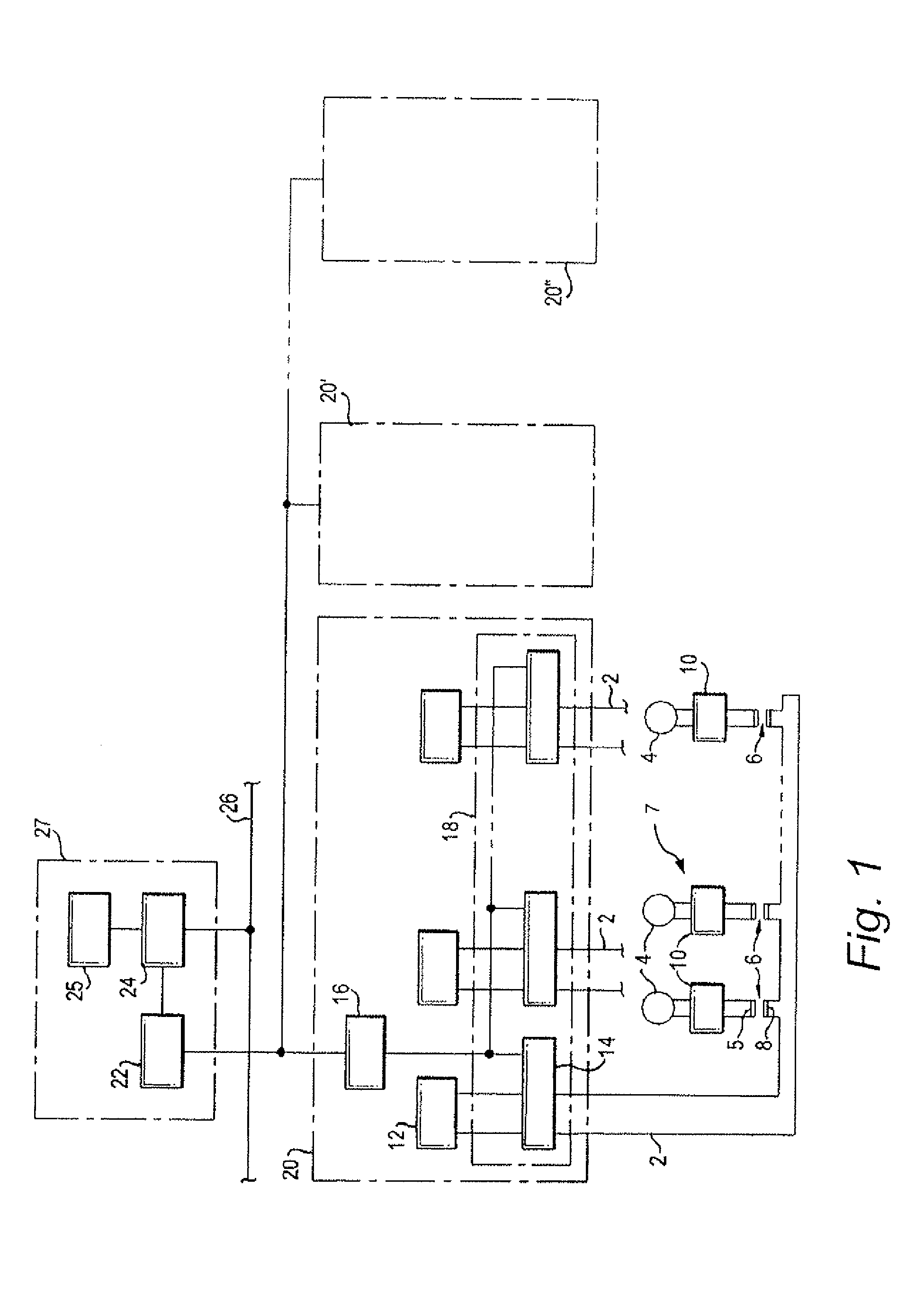
[0030]With reference to FIG. 1, an airfield lighting monitoring system includes a number of current supply loops 2 for LEDs 4, only one of said loops 2 being shown in its entirety in the Figure. Each LED 4 is connected to its associated loop 2 via a secondary winding 5 of an isolation transformer 6, the primary winding 8 of which is series connected in the current supply loop, and via a light monitor switch (LMS) 10. Each current supply loop 2 is fed by a constant current regulator (CCR) 12 via a communicating Series Circuit Modem (SCM) 14. A concentrator unit (CU) 16 is connected in a serial or network communication configuration to a group 18 of the communicating units 14.

[0031]The CU unit 16 and its associated elements, described above, together form a sub-unit 20, which can e.g. be devoted to a certain part of the lighting system of an airfield. The lighting system can include a required number of similar sub-units, of which some are indicated at 20′ and 20″.

[0032]The CU units 1...


PUM


Abstract

A method of feeding electric power to an LED (4) in an airfield lighting unit (7). The method comprises the steps of: feeding a constant alternating current (Is) to a rectifier (40), rectifying the alternating current (Is) to a rectified current (Ir), pulse width modulating the rectified current (Ir), charging a capacitor (43) with the pulse width modulated rectified current (Ir), and feeding the LED (4) with power from the capacitor (43).

Description

TECHNICAL FIELD[0001]The present invention relates to a method, a unit and a system for feeding power to LED airfield lighting.BACKGROUND ART[0002]At airports, lighting systems are used for directing airplanes during landing and taxiing. These lighting systems have a large number of light sources and it is important they are operated properly and that failed light sources are replaced quickly, especially during times of low visibility. Otherwise, the consequences of a plane missing a taxiway or a stop signal can be disastrous. Since visual light source inspection increases the risk for an accident and induce costs, automatic lamp monitoring systems have been developed.[0003]Light sources in these lighting systems are frequently connected into a so-called series circuit using an isolation transformer for each light source.[0004]Such light sources are connected in series via a power cable and fed by a constant current power supply from a constant current regulator (CCR). Traditionally...

Claims


Application Information

Patent Timeline
IPC IPC(8): H05B41/30H05B44/00
CPCH05B33/0818H05B37/038H05B37/036H05B33/0851H05B45/10H05B47/23H05B47/235H05B45/382
Inventor FORSSEN, JOHANHAKANSON, OLA
Owner SAFEGATE INT
Why Eureka
Try Eureka