Position Sensor

a technology of position sensor and sensor body, which is applied in the direction of electrical/magnetically converting sensor output, electric/magnetic position measurement, instruments, etc., can solve the problems of mechanical vibration, bearing wear, and present sensor is insensitive to system wear, etc., to achieve higher spatial resolution, more robustness, and low cost. easy to manufacture

Inactive Publication Date: 2009-04-09
SALUNDA LTD
View PDF9 Cites 10 Cited by
  • Summary
  • Abstract
  • Description
  • Claims
  • Application Information

AI Technical Summary

Benefits of technology

[0005]Thus, there is provided an accurate position sensor for sensing linear or angular position. A position sensor according to the present invention has a number of advantages over previous sensors, as described below.
[0006]The present position sensor is more robust than previous sensors and is not vulnerable to failure or malfunction due to ingress of dust or oil. The present sensor is invulnerable to D.C. drift, and experiences none of the problems usually introduced by 1 / f noise. In addition, the present sensor is compact, as well as being inexpensive and easy to manufacture. The present sensor can operate whilst immersed in fluid, or at high temperatures, and is generally tolerant of hostile environments. Higher spatial resolution is possible with the present position sensor than with prior art sensors. Furthermore, the present sensor is insensitive to system wear, bearing wear, and the effects of mechanical vibration. The active life of the present sensor is expected to exceed that of a variable capacitance sensor. The length of the present sensing device is less than the required length of a linearly variable transformer for a given measuring range and resolution. Moreover, the present sensor is easily temperature compensated and is therefore ideally suited to non-thermostatic applications.
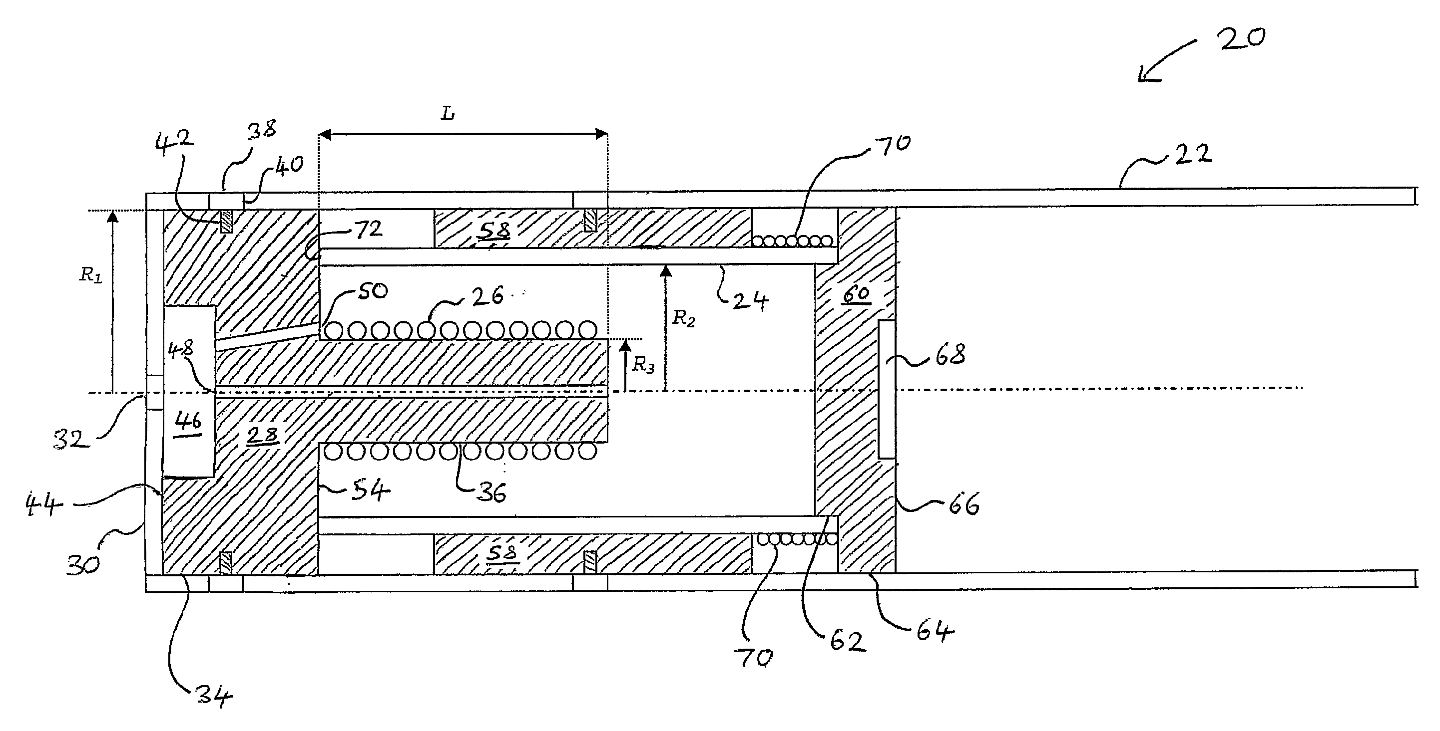
[0010]In a further preferred embodiment, there is provided a linear position sensor in which the screen comprises an outer screen adapted to receive the coil, and a long tapered part, such as a wire or rod, disposed axially through the coil. The long tapered part is moveable in an axial direction relative to the coil such that the flux compression is related to the axial position of the long tapered part relative to the coil. The sensor is insensitive to sideways movement of the long tapered part and thus should give an output proportional to the diameter of the long tapered part without the need for precise centring. In this way, the sensor is insensitive to machining error, and mechanical wear, etc.

Problems solved by technology

Furthermore, the present sensor is insensitive to system wear, bearing wear, and the effects of mechanical vibration.

Method used


Image

  • Position Sensor
  • Position Sensor
  • Position Sensor

Examples


first embodiment

[0122]In a dual lane position sensor according to the present invention, two coils are interwound. One set of electronics operates both coils alternately. This is achieved by rapid switching between coils by means of a three-position switch. The sequence of operation would be as follows (or similar): coil 1 active, both coils active, coil 2 active. The coils would be perfectly coupled, the output therefore for a given position input is expected to be identical in all three operating regimes. It will be appreciated that any of the linear or angular position sensors described above could be modified to become a dual lane position sensor of this type.

second embodiment

[0123]a dual lane position sensor 200 is shown in FIG. 9. Two coils 202 and 204 are arranged within a screen 206. The screen 206 is symmetrical about a line AA′ in FIG. 9, with each half having a profile similar to that of the tapered screen embodiment of FIG. 3b (so as to obtain a linear response).

[0124]The coils may be set into an insulating rod 208, made of epoxy, for example. Thus, by moving the rod 208, the coils 202 and 204 may be moved axially within the screen 206. An inner surface 210 of the screen 206 is conducting. It may be machined, or injection moulded from plastic; if it is injection moulded, the screen 206 may be metal-plated either on the inside or the outside. Either would result in a satisfactory screen. The two coils 202 and 204 may be operated by separate electronics.

third embodiment

[0125]a dual lane position sensor 210 is shown in FIG. 10. The sensor 210 comprises two independently operating coils 212 and 214 built into a simple dual-lane system. The flux is confined by an outer screen 216 and an inner screen 218. The inner screen 218 is moveable relative to the coils 212 and 214.


PUM


Abstract

There is described a position sensor comprising a sensor electromagnetic field generator, a screen arranged to confine the sensor electromagnetic field, and an output. The output is arranged to provide a signal which varies in dependence upon an amount of flux compression of the electromagnetic field resulting from the presence of the screen. The amount of flux compression is related to a position of the screen in relation to the sensor electromagnetic field generator. There is also described a method of detecting a relative position of an electromagnetic field generator and a screen.

Description

FIELD OF THE INVENTION[0001]The present invention relates to a position sensor for detecting linear and / or angular position, and to a method of position sensing.BACKGROUND OF THE INVENTION[0002]Many types of position sensors are currently available for detecting linear and / or angular position. For high resolution position detection, conventional variable capacitance sensors may be used. Alternatively, linear variable transformers may be used, but these are generally expensive and bulky. Moreover, the associated temperature compensation of these prior art sensors can be difficult. In addition, such sensors are rendered useless by the presence of oil or cutting fluid on their active surfaces, and will not work when immersed in fluid.SUMMARY OF THE INVENTION[0003]Against this background there is provided, in accordance with a first aspect of the present invention, a position sensor comprising a sensor electromagnetic field generator, a screen arranged to confine the sensor electromagne...

Claims


Application Information

Patent Timeline
Patent Type & Authority Applications(United States)
IPC IPC(8): G01B7/00
CPCG01D5/20G01B7/003G01D5/2006
Inventor KARENOWSKA, ALEXY DAVISONGREGG, JOHN FRANCIS
Owner SALUNDA LTD
Why Eureka
Try Eureka