Laser area sensor

a laser area sensor and sensor technology, applied in the field of laser area sensors, can solve the problems of inability to easily set up a suitable surveillance area, detect an intruder erroneously, etc., and achieve the effect of improving the reliability of detecting the human body

Active Publication Date: 2009-04-09
OPTEX CO LTD
View PDF7 Cites 20 Cited by
  • Summary
  • Abstract
  • Description
  • Claims
  • Application Information

AI Technical Summary

Benefits of technology

[0023]With thus configured laser area sensor, an arbitrary surveillance area can be easily set according to factors such as an actual installation location and a surveillance purpose. Accordingly, the reliability in detecting a human body can be improved.

Problems solved by technology

Thus, it may be erroneously detected that an intruder is present, for example, when the distance data or the angle data is changed by the swaying of plants in the wind, the entering of objects such as birds or small animals, or other noise factors.
Moreover, according to an object identifying method using an area sensor as in Patent Document 2 above, although the reliability in detecting a human body itself is improved compared with that of Patent Document 1, an area in which a human body is to be detected needs to be determined and set in advance, and thus a suitable surveillance area cannot be easily set according to factors such as an actual installation location and a surveillance purpose.

Method used


Image

  • Laser area sensor
  • Laser area sensor
  • Laser area sensor

Examples


first embodiment

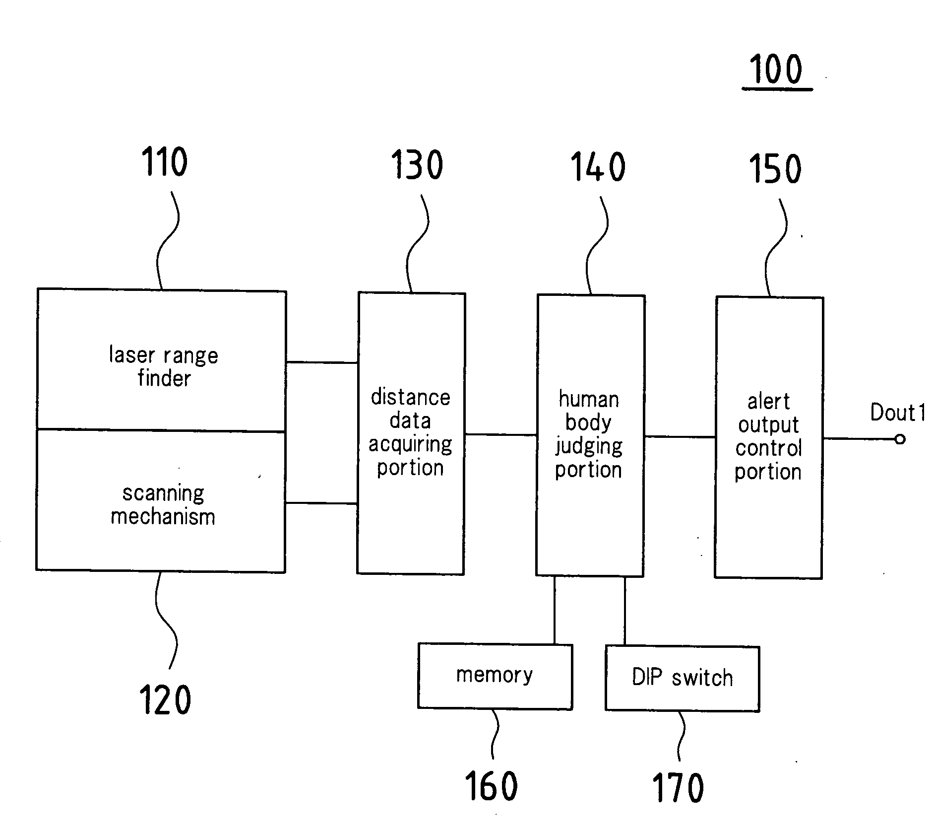
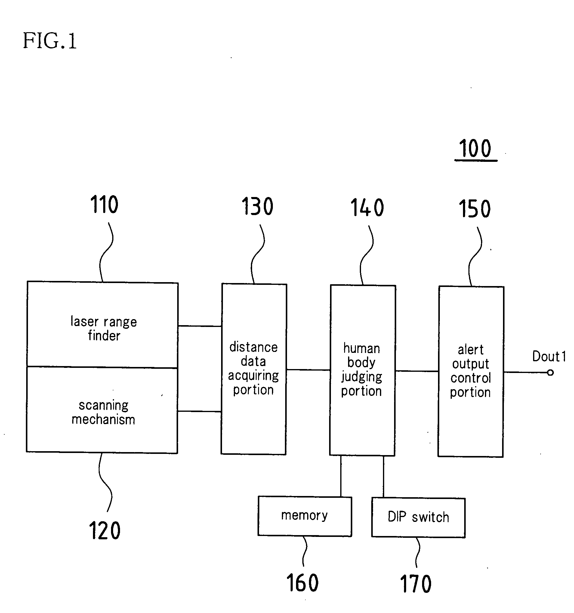
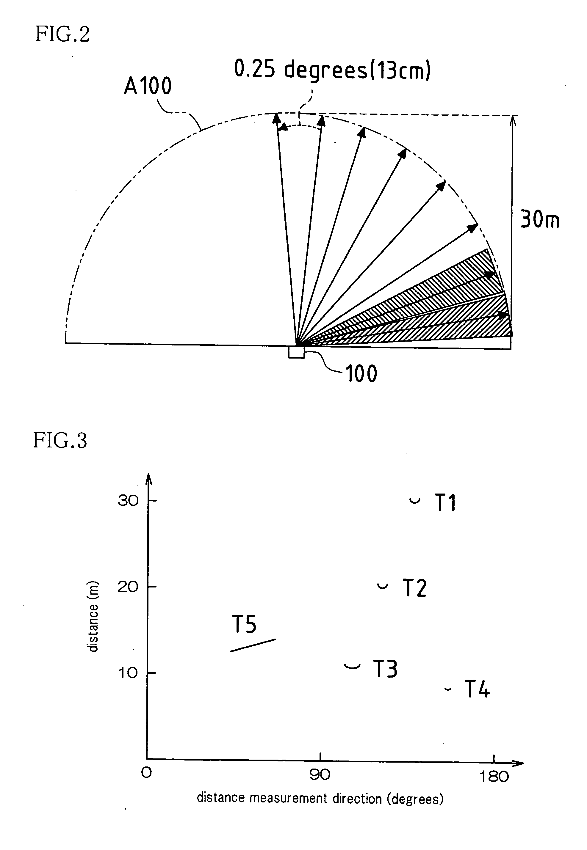
[0035]FIG. 1 is a block diagram showing the schematic configuration of a laser area sensor 100 according to a first embodiment of the present invention. FIG. 2 is a schematic explanatory view of a detection area defined by the laser area sensor 100. FIG. 3 is an explanatory graph showing an example of distance data acquired by the laser area sensor 100. In FIG. 2, the interval between adjacent distance measurement directions is shown much wider than the actual interval, for the sake of explanation.

[0036]As shown in FIG. 1, the laser area sensor 100 includes a laser range finder 110, a scanning mechanism 120, a distance data acquiring portion 130, a human body judging portion 140, an alert output control portion 150, a memory 160, and a DIP switch 170.

[0037]The laser range finder 110 emits pulsed laser light, and precisely measures an extremely short period of time for reflected light to return from an object that is present in a laser light emitting direction, thereby accurately mea...

second embodiment

[0058]FIG. 5 is a schematic explanatory view of a normal detection area A1 in a case where a laser area sensor 200 according to a second embodiment of the present invention is installed on a building wall face 10a in order to exercise surveillance over an area enclosed on three sides by a building 10 having a slightly atypical shape. FIG. 6 is a schematic explanatory view of an erroneous operation preventing detection area A2 in a case where the laser area sensor 200 is turned to a mode for preventing erroneous operations in the vicinity of the wall face. The configuration and the like of the laser area sensor 200 itself are substantially similar to those of the laser area sensor in the first embodiment, and thus different points will be mainly described below.

[0059]As described in the first embodiment, the laser area sensor 200 acquires distance data in each direction at predetermined angle intervals in a detection area having a radius of several to several tens of meters centered ...

third embodiment

[0070]In the second embodiment described above, the information of the actual detection area A1 at the installation location is stored, and, if necessary, the erroneous operation preventing detection area A2 also can be selected in which a position that is inward by the predetermined distance d1 from each portion recognized in advance as a wall face or the like is taken as a new boundary. However, an arbitrary surveillance area cannot be set. Thus, a laser area sensor in which an arbitrary surveillance area can be easily set according to factors such as an actual installation location and a surveillance purpose will be described below as a third embodiment.

[0071]FIG. 7 is a schematic explanatory view of a method for setting an arbitrary surveillance area A3 in a case where a laser area sensor 300 according to a third embodiment of the present invention is installed on the building wall face 10a in order to exercise surveillance over an area enclosed on three sides by the building 10...


PUM


Abstract

In an embodiment, a laser area sensor of the present invention comprises: a laser range finder; a scanning mechanism that changes a measurement direction of the laser range finder; a distance data acquiring portion that defines a detection area and acquires distance information in each direction in the detection area in a time-series manner, by periodically causing the laser range finder to perform measurement while causing the measurement direction to be changed; a human body judging portion that extracts a portion that is presumed to correspond to a human body, from among the distance information and judges whether or not the extracted portion matches a human body based on a time-series moving status of the extracted portion; an alert output control portion; a memory; and a DIP switch.

Description

CROSS-REFERENCE TO RELATED APPLICATIONS[0001]This application claims priority under 35 U.S.C. §119(a) on Patent Application No. 2007-263582 filed in Japan on Oct. 9, 2007, the entire contents of which are herein incorporated by reference.BACKGROUND OF THE INVENTION[0002]1. Field of the Invention[0003]The present invention relates to a laser area sensor that detects, for example, an intruder or the like in the building premises. In particular, the present invention relates to a laser area sensor with improved reliability in detecting an intruder or the like using the laser area sensor.[0004]2. Related Art[0005]Conventionally, as one type of crime prevention apparatuses, a microwave sensor is known that transmits microwaves toward a detection area, and, if an intruder is present in the detection area, receives waves reflected by the intruder and detects the intruder.[0006]Also, a “security system” for detecting an intruder using a laser range finder that adopts laser light as a light ...

Claims


Application Information

Patent Timeline
Patent Type & Authority Applications(United States)
IPC IPC(8): G08B13/18G01S17/04
CPCG01S17/026G08B13/187G01S17/50G01S17/42G01S17/04
Inventor IWASAWA, MASASHI
Owner OPTEX CO LTD
Why Eureka
Try Eureka